

Manufacturing Solutions
Precision parts · Practical engineering · Measurable acceptance
Choose the Right Process for Your Precision Part
Start with the dimensions that control fit and function. Compare machining routes, review materials and finishing, and define the evidence your team needs to approve production.
Request a Drawing ReviewSee Equipment Data

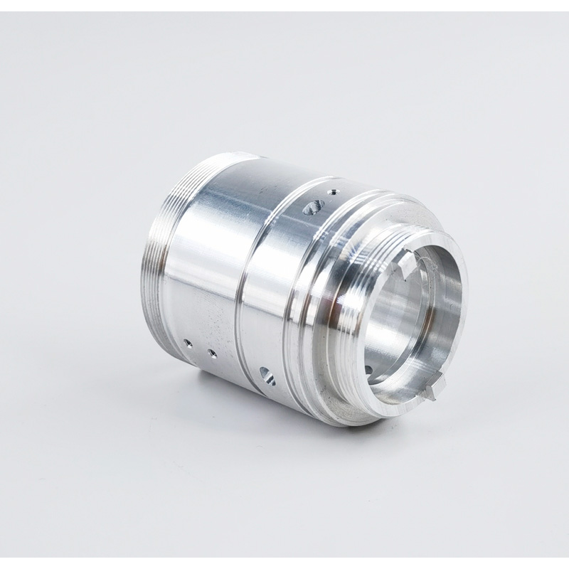
Complex blade geometry · Hub interfaces · Profile inspection
Listed CNC machining and drill-tap centers, including the five-axis groups.
Five-axis-class units within the 46-center total.
CMMs with a listed 600 × 800 × 600 mm measuring range.
Mitutoyo micrometers across the listed 0–25 and 0–50 mm ranges.
Start with the problem
What does your part need to achieve?
Reliable fit and assembly
Bearing seats, locating bores and mating faces need a shared datum strategy. Send assembly information and identify the interfaces that control function.
Discuss critical dimensions →Lower weight without losing function
Thin walls, pockets and complex geometry require a practical machining and inspection approach. Review wall stability, tool access and fixture support.
Read the thin-wall guide →Comparable quotes and fewer surprises
Make material grade, quantity, finish, inspection documents and delivery scope explicit so purchasing decisions compare the same requirements.
Use the RFQ checklist →Process selection
Geometry, materials, finish and acceptance—in one place
Machining and inspection data below come from the supplied equipment register. Additional process routes require quotation-stage capacity confirmation. Manufacturer benchmarks are identified separately from factory inventory.
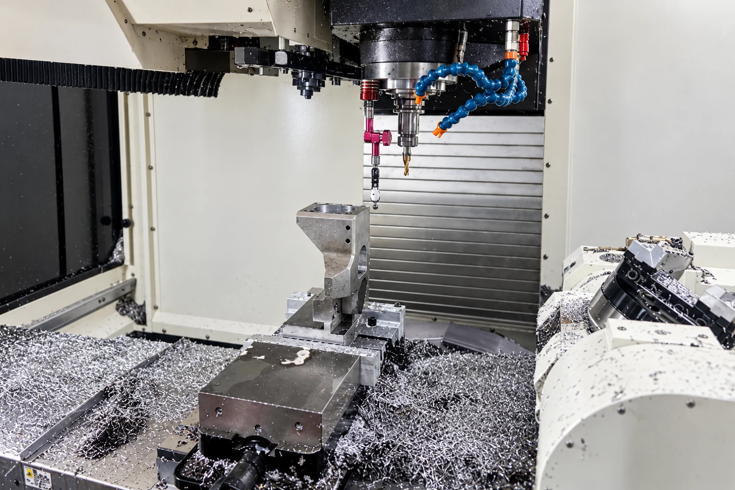
Listed machining equipment
Prototype Machining
Functional prototypes that help engineering teams check fit, assembly and design changes before committing to production tooling.
Size & equipment
CNC register: planar range listed up to 1,300 × 1,600 mm. Z height, fixture clearance and the usable part envelope require drawing review.
Precision & acceptance
Define mating faces, bore positions and assembly fits on the drawing. The CNC register lists a precision value of 0.01; this is not a blanket part tolerance.
Material selection
Aluminum, stainless steel, steel, brass, copper and engineering plastics are material options to discuss. Specify the exact grade and condition; availability is confirmed in the quote.
Surface finishing
Discuss deburring, bead blasting, anodizing, plating, painting or polishing against material compatibility. Mask or compensate critical fits where coating thickness matters.
Tooling & lead time
Prototype lead time is quoted after CAD, material, quantity, finish and inspection scope are agreed. Identify your required sample date and any assembly trial.
Inspection focus
Compare the approved drawing revision with critical dimensions, surface condition, fit and assembly function.
Retouched original website photograph.
Review This Process →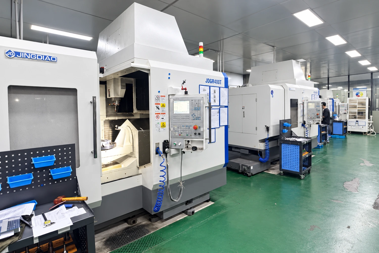
Listed machining equipment
5-Axis CNC Machining
Complex surfaces, inclined holes and features on multiple faces need a coordinated datum, fixture and tool-access strategy.
Size & equipment
16 five-axis-class units are listed across three equipment groups. For JDGR400T, the manufacturer specifies X/Y/Z travel of 450 × 680 × 400 mm. Travel is not the maximum finished-part size.
Precision & acceptance
The high-speed five-axis group lists a precision value of 0.005. Specify profile, position, runout and datum relationships separately; finished-part capability is reviewed per feature.
Material selection
Material grade, hardness and stock condition affect cutting strategy. Discuss aluminum, steel, stainless steel, brass or copper against your part geometry.
Surface finishing
Discuss as-machined surfaces, controlled deburring and compatible finishing. State roughness requirements on functional surfaces rather than requesting a uniform finish everywhere.
Tooling & lead time
Programming, setup, roughing, finishing and inspection are included in the quotation review. Complex fixturing or difficult tool access can change sample timing.
Inspection focus
Agree the datum alignment, profile measurement, critical bore checks and CMM report scope before first-piece approval.
Retouched original website photograph.
Review This Process →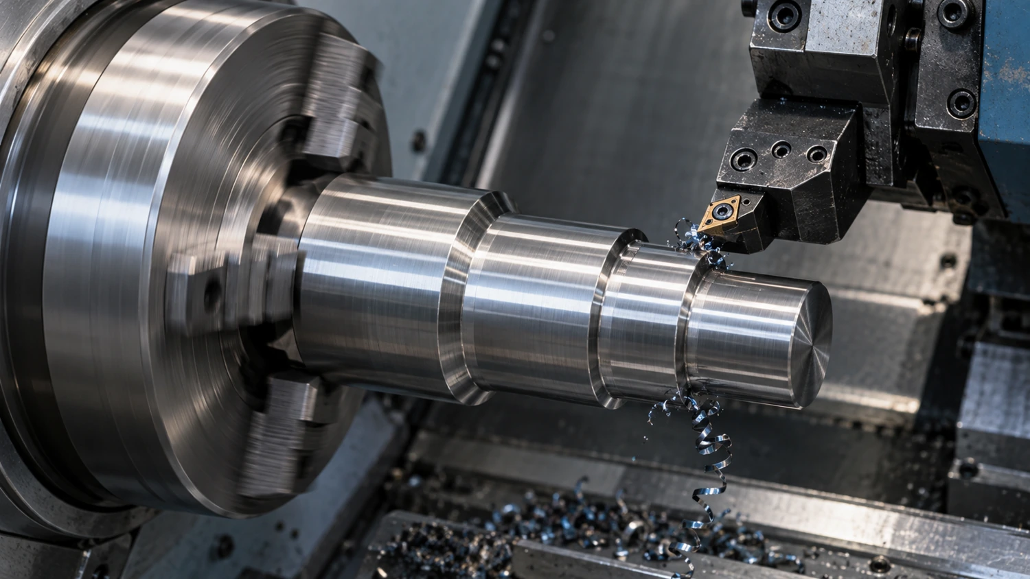
Listed machining equipment
Precision CNC Turning
Shafts, sleeves, bushings and threaded parts need controlled diameters and relationships between rotational features.
Size & equipment
Swiss-type machines: listed diameter range Ø0.5–Ø26 mm, 2 units. Turn-mill machines: listed diameter Ø250 mm, 4 units. Six additional CNC lathes are listed; their maximum diameter and usable length need confirmation.
Precision & acceptance
The Swiss-type group lists a precision value of 0.005. Specify fit diameters, roundness, coaxiality, runout and finish on the features that control function.
Material selection
Discuss machinable grades of aluminum, stainless steel, steel, brass and copper. State heat treatment and material certification requirements in the RFQ.
Surface finishing
Discuss deburring, passivation, plating, anodizing, polishing or grinding where applicable. Define edge breaks and protect threads and fit surfaces.
Tooling & lead time
The quote considers bar or blank availability, setup, cycle complexity, secondary operations and inspection. Include prototype and production quantities separately.
Inspection focus
Define inspection for bores, threads, shoulders and runout. Confirm a practical method for long, slender or internally featured components.
Process image supplied for presentation; machine ownership and project capacity are confirmed separately.
Review This Process →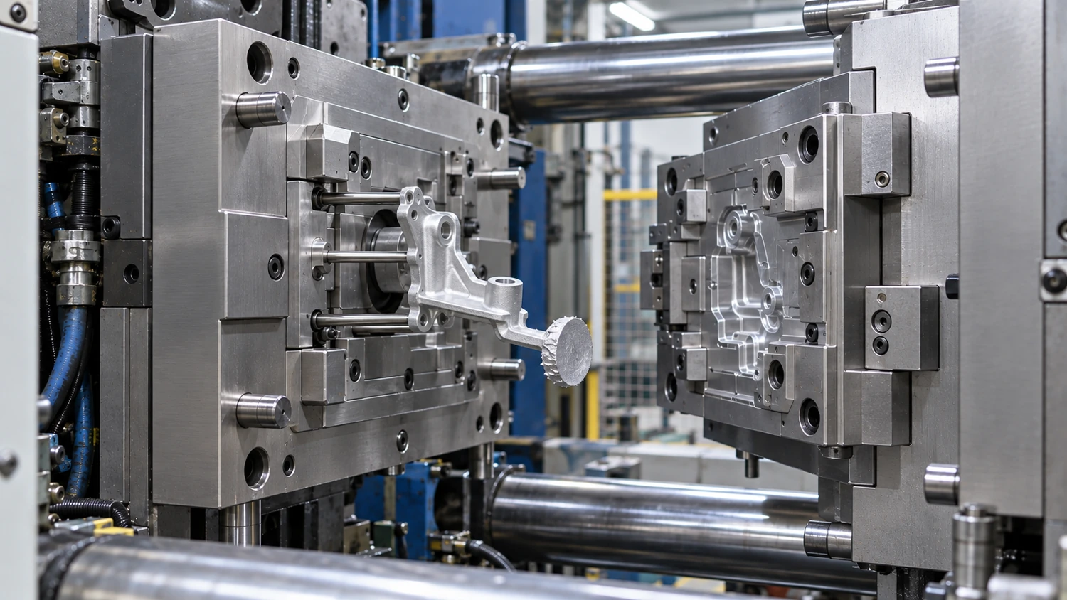
Project route · quotation review
Aluminum Die Casting
For repeat aluminum housings, covers and brackets, assess tooling investment, filling, shrinkage and secondary machining together.
Size & equipment
Maximum L × W × H and casting weight are confirmed after projected area, wall thickness, cavity count, runner design and the selected press are reviewed. Press tonnage alone does not establish a maximum part size.
Precision & acceptance
Separate as-cast dimensions from machined bearing seats, sealing faces and threads. Specify dimensional tolerances and the casting standard/revision in the RFQ; confirm what needs secondary CNC machining.
Material selection
The supplied industry reference documents aluminum alloy castings. Specify the required alloy grade and material standard. Zinc, magnesium and specific aluminum grades are not confirmed by the equipment register.
Surface finishing
Discuss trimming, deburring, shot blasting, polishing, powder coating or liquid painting. Anodizing appearance is alloy- and process-dependent and requires sample approval.
Tooling & lead time
Mold design → tool machining → first trial → dimensional review → corrections → sample approval. Quote the tooling schedule and production schedule separately; mold complexity and trial corrections determine the committed dates.
Inspection focus
Agree porosity/leak requirements where relevant, machined datum inspection, cosmetic acceptance, material documents and sample approval before series production.
Process image supplied for presentation; machine ownership and project capacity are confirmed separately.
Review This Process →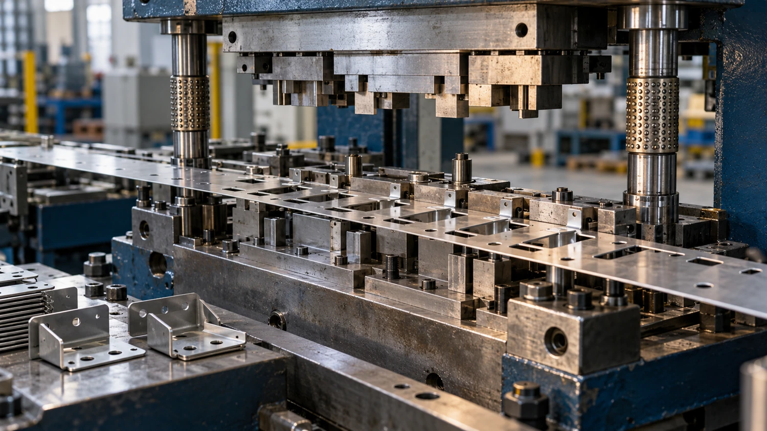
Project route · quotation review
Metal Stamping
Repeat sheet components need a stable strip layout, die design and controlled forming sequence.
Size & equipment
Review blank L × W, stock thickness, strip width, die envelope and press force. A reference Schuler CFL100 press has 1,000 kN force and a 950 × 660 mm bed; these are equipment benchmarks, not an LXCET part-size commitment.
Precision & acceptance
Set hole position, formed dimensions, burr direction and flatness requirements. Die wear, stock variation and forming springback affect repeatability; approve the first-off inspection plan.
Material selection
Discuss low-carbon steel, stainless steel, aluminum, brass or copper sheet against formability and the specified grade. Thickness and temper must be stated.
Surface finishing
Consider deburring and compatible plating, painting or powder coating. Specify which faces are cosmetic and where edge exposure or electrical contact must remain.
Tooling & lead time
Separate die build, trials, approval and production. Include annual volume and order quantities so engineering can assess simple dies versus progressive tooling.
Inspection focus
Check formed geometry, hole locations, burrs, material thickness and critical assembly dimensions against the approved sample.
Process image supplied for presentation; machine ownership and project capacity are confirmed separately.
Review This Process →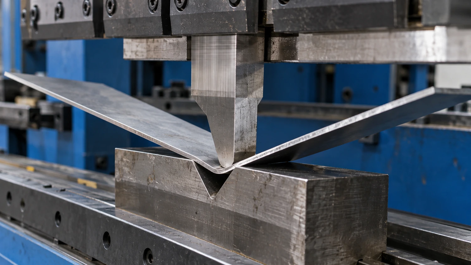
Project route · quotation review
Sheet Metal Bending
Enclosures, panels and supports need realistic bend radii, flange lengths and tool access to assemble correctly.
Size & equipment
Review flat blank, bend length, thickness, minimum flange and tool clearance. A reference TRUMPF TruBend 3100 specifies 3,230 mm bending length and 1,000 kN press force; the available production route is confirmed in the quote.
Precision & acceptance
Define finished dimensions and bend angles, not only the flat pattern. Material direction, springback and bending sequence affect fit; specify the critical assembly interfaces.
Material selection
Discuss aluminum, stainless steel, steel, brass or copper sheet. Confirm grade, thickness, temper and bend direction before freezing the flat pattern.
Surface finishing
Discuss deburring, brushing, painting, powder coating or compatible plating. Define visible faces, grain direction and protection during forming.
Tooling & lead time
The quote covers cutting, bending, finishing and any hardware insertion or assembly. Prototype validation should precede repeat production for fit-critical enclosures.
Inspection focus
Check bend angles, flange dimensions, hole-to-bend relationships, cosmetic faces and overall assembly fit.
Process image supplied for presentation; machine ownership and project capacity are confirmed separately.
Review This Process →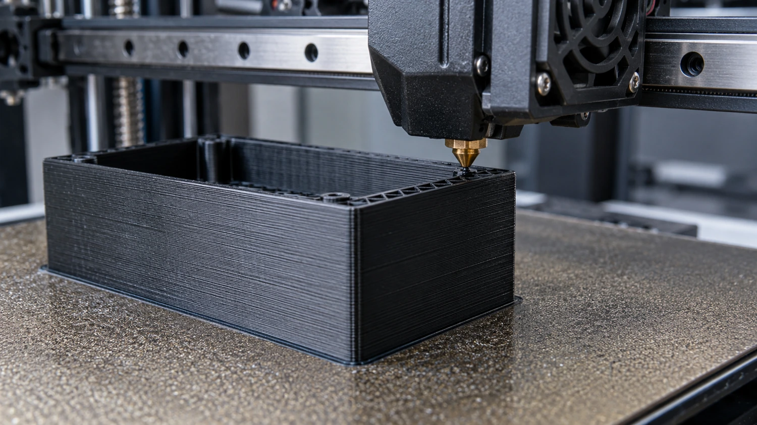
Project route · quotation review
3D Printing
Use additive prototypes to evaluate shape, access and assembly before selecting the final manufacturing route.
Size & equipment
Select the printing technology and available build volume first. A reference Stratasys F170 FDM printer has a 254 × 254 × 254 mm build envelope. Larger models may require another platform or a split design.
Precision & acceptance
Fit depends on process, orientation, supports and material. For the F170 reference, manufacturer accuracy is ±0.200 mm or ±0.002 mm/mm, whichever is greater, with geometry dependence and additional Z allowance of −0/+layer height; this is not an LXCET guaranteed tolerance.
Material selection
Choose the process around function: polymer FDM, resin or metal printing have different material choices. Confirm the exact material, temperature limits and load direction before ordering.
Surface finishing
Discuss support removal, sanding, painting or machining of selected interfaces. Layer lines and support-contact surfaces should be included in cosmetic acceptance.
Tooling & lead time
Build orientation, machine availability, support removal and finishing determine the quote. State whether the sample is for appearance, fit or functional testing.
Inspection focus
Inspect dimensions important to fit, support-contact areas and orientation-sensitive features. Printed material properties do not automatically match machined stock.
Process image supplied for presentation; machine ownership and project capacity are confirmed separately.
Review This Process →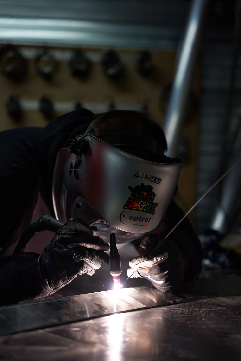
Project route · quotation review
Welding & Assembly
Fabricated frames and subassemblies need an agreed joint design, fixture strategy and dimensional release plan.
Size & equipment
Overall L × W × H, material thickness, joint access and fixture support determine feasibility. Welding power-source capacity alone does not define maximum assembly size.
Precision & acceptance
Control distortion with the agreed sequence and fixtures. Define final datums, assembly dimensions, weld requirements and whether post-weld machining is needed.
Material selection
Discuss steel, stainless steel or aluminum only after grade, thickness, filler compatibility and the applicable welding requirements are reviewed.
Surface finishing
Discuss weld dressing, grinding, polishing, cleaning and compatible coatings. Grinding or polishing is a finishing operation, not a dimensional inspection method.
Tooling & lead time
Separate fixture preparation, joining, cooling, inspection, finish and assembly. Request any weld procedure or welder qualification required by your program before quotation.
Inspection focus
Agree visual weld acceptance, final dimensions, fit, coating and any specified nondestructive testing. Testing scope and external services must be confirmed in the quote.
Welding process photograph: Valentin Saumon / Pexels. Process imagery does not document LXCET-owned equipment.
Review This Process →Factory equipment register
Traceable equipment data for your drawing review
Use the listed ranges to start a feasibility discussion. Working travel, fixture space and finished-part envelope are different measurements.
| Equipment group | Model / family | Qty | Listed range / travel (mm) | Listed precision value* |
|---|---|---|---|---|
| High-speed five-axis centers | Jingdiao / JS; JDGR400T / JS-UD40 | 8 | 400–500 listed; JDGR400T maker travel 450 × 680 × 400¹ | 0.005 |
| U320 five-axis group | ZF-T6 AL-5 | 6 | 400–600 listed | 0.01 |
| CNC machining centers | T5 / 850 / 1370 / 1613 | 15 | Up to 1,300 × 1,600 planar range; Z not given | 0.01 |
| 3-axis drill-tap centers | T-600 heavy-cut type | 9 | 600–700 listed | 0.01 |
| 4-axis drill-tap centers | T-600 | 6 | 600–700 listed | 0.01 |
| 5-axis drill-tap centers | T-600 | 2 | 600–700 listed | 0.01 |
| Swiss-type turning | Zhongcong; model not stated | 2 | Ø0.5–Ø26 | 0.005 |
| CNC lathes | 46 gang-tool / 52 turret | 6 | 0–600 listed; axis and diameter not defined | 0.01 |
| Turn-mill machines | K-46BTY | 4 | Ø250 listed | Not normalized² |
| Slow-wire EDM | Sodick ALN400GS | 3 | 550 × 380 × 220 listed | 0.002 |
| Slow-wire EDM | Seibu M50HP | 2 | 500 × 400 × 310 listed | 0.002 |
| Surface grinder | KGS615W | 2 | 400 × 800 listed | 0.002 |
* Precision values are transcribed from the supplied register, which does not define their units, sign, test method or whether they describe positioning or finished-part performance. They are not guaranteed part tolerances. Single-axis ranges are retained as listed; missing axes are not inferred. ¹ JDGR400T X/Y/Z travel is a manufacturer reference for that model, not a count or specification for every machine in the mixed group. ² The K-46BTY precision entry has ambiguous spacing and has not been converted into a tolerance claim.
Quality & inspection
Inspection resources matched to the features that matter
Two Serein / Hexagon CMMs are listed with a 600 × 800 × 600 mm measuring range. The register also includes optical, height, hardness and surface-finish measurement equipment.
Explore Quality & InspectionListed inspection resources
- 2 CMMs; measuring range 600 × 800 × 600 mm.
- 2 optical projectors; 50× magnification.
- 1 height gauge; range 0–600 mm.
- 1 vision measuring system; range 300 × 200 mm.
- 1 Rockwell hardness tester and 1 surface roughness tester.
- 40 Mitutoyo micrometers at 0–25 mm; 20 at 0–50 mm.
Calibration status, measurement uncertainty, probe access and report requirements must be agreed for the project. Grinding and polishing are finishing operations, separate from inspection.
Engineering references
Understand the numbers before choosing a route
Machine specifications and factory capability are different
The equipment register establishes listed inventory. Manufacturer information below provides process-planning references for identified models. TRUMPF, Schuler, Stratasys and Fronius equipment is not listed in the supplied factory register and is not represented as LXCET-owned.
Jingdiao JDGR400T manufacturer brochure · TRUMPF TruBend Series 3000 · Schuler sheet-forming equipment brochure · Stratasys F170 specification sheet
What information establishes a die-casting commitment?
Confirm alloy, casting weight, projected area, cavities, mold design, as-cast dimensions, secondary machining, cosmetic criteria and sample approval. The supplied aluminum die-casting industry reference describes aluminum castings and finishing routes; it does not establish LXCET equipment ownership, maximum part dimensions, guaranteed tolerance or mold lead time.
What does welding equipment data tell us?
A reference Fronius iWave 230i AC/DC has a 3–230 A welding-current range. Current capacity alone cannot establish assembly dimensions, weld qualification or final dimensional tolerance.
Applications
Explore the engineering demands in your industry
Find representative component concepts, material options, process considerations and machining challenges for your application.
Application examples are design references. Regulated programs require project-specific qualification, documentation and approvals.
A practical project handover
Help engineering and purchasing work from the same brief
Send a 3D model together with a dimensioned drawing. A model describes geometry; the drawing communicates tolerances, material, finish and acceptance requirements.
Visit Our Factory PageInclude these items in your RFQ
- CAD files and a dated, revision-controlled drawing.
- Material grade, heat treatment and surface finish.
- Prototype quantity and expected production quantities.
- Critical assembly features and inspection documents.
- Target delivery date, destination and packaging needs.
Your next project
Start with your drawing and the problem you need to solve.
Tell us what must fit, what must perform and what evidence your team needs to approve the parts.
Discuss Your ProjectEmail Tony Zhou