

Drones · Drawing-based custom machining
CNC Machined Drone Frame Components: Application & Engineering Review
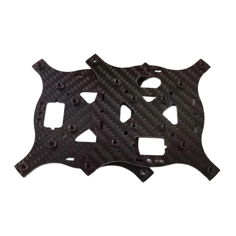
Lightweight frame and mounting geometry for a reviewed UAV assembly. This component geometry is presented to help engineering and purchasing teams specify a custom part. Final material, dimensions and suitability are defined by your approved design.
What problem should this part solve?
Reducing mass can make arms and pockets sensitive to clamping distortion and vibration during machining. Start with the functional interfaces so that manufacturing and inspection work from the same acceptance criteria.
Material, process and inspection plan
| Application | Lightweight frame and mounting geometry for a reviewed UAV assembly. |
|---|---|
| Manufacturing route | CNC milling and drilling of the selected stock material with support for thin or extended features. |
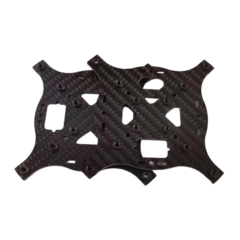
| Material options to review | Select aluminum or a separately reviewed composite route; the existing dark frame photo does not verify material grade. |
| Surface finish to specify | Edge control and compatible protection. Composite edges and aluminum surfaces require different acceptance criteria. |
| Critical inspection features | Mounting-hole positions, arm geometry, flatness after release and damage-free edges. |
| Dimensions & tolerance | Made to the approved customer drawing. Supply overall dimensions in mm, datums, fits and feature-specific tolerances; final capability is confirmed after engineering review. |
| Prototype & production | Quote sample and repeat-order quantities separately. Lead time, inspection documents and delivery scope are confirmed in the quotation. |
Machining difficulty and practical solution
CNC milling and drilling of the selected stock material with support for thin or extended features. Mounting-hole positions, arm geometry, flatness after release and damage-free edges are the features to prioritize in the setup and inspection plan. Review tool access and workholding before freezing the drawing; agree any secondary operation rather than assuming it is included.
RFQ and sample approval checklist
Provide the CAD model and revision-controlled drawing, exact material grade, mounting-hole positions, arm geometry, flatness after release and damage-free edges, required finish and prototype/production quantities. Identify the features that control assembly and state the reports needed for release.
- Approve the first-piece measurement scope and the applicable drawing revision.
- Confirm material documents, final finish and packaging needed for your assembly.
- Review the sample against mating parts before approving repeat production.
Can LXCET review a custom version?
Send your drawing for a feasibility review of custom CNC machined UAV frame components. The equipment and process guide explains listed machine ranges; the quality and inspection page explains how to define acceptance evidence. A machine’s travel or listed precision value is not a universal finished-part tolerance.
Request a Drawing Review → tonyzhou@lxcet.com
Related Drones components
Technical reference and image scope
Thin and slender features should be reviewed for tool access and deflection. Protolabs CNC machining design guidance.
Product photograph from the existing LXCET media library. Application descriptions are engineering review examples, not claims of a delivered customer program, certification or tested service rating. Material cannot be verified from appearance alone.