

Blog

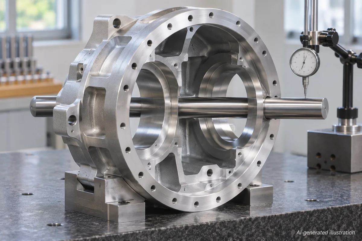
A robot joint housing can have the correct individual bore sizes and still assemble badly. If the bearing seat, mounting face and locating holes are referenced inconsistently, the complete assembly may bind or require adjustment. The practical starting point is a shared datum plan for machining and inspection, followed by checks in the condition specified on the drawing.
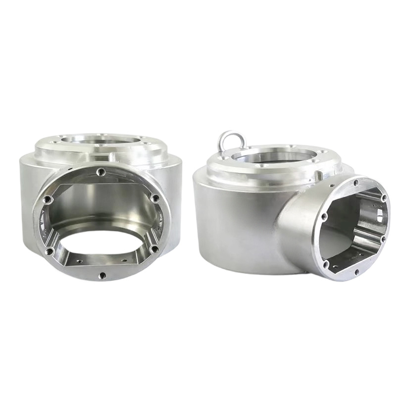
Start with how the housing fits the assembly
Before choosing a fixture, identify the surfaces that locate the housing in service. Ask which face seats against the mating component, which feature locates the rotation axis, and which holes establish orientation. A convenient stock face is not automatically the right functional datum.
Agree these relationships on the drawing before production. Specify the relevant size and geometric requirements for the actual assembly; avoid applying the tightest tolerance to every surface. If the drawing and 3D model disagree, resolve that difference before cutting metal.
Three common symptoms and what to investigate
| Assembly symptom | Possible process issue | Useful check |
|---|---|---|
| The bearing fits, but the shaft binds | Related seats or faces are not aligned as intended | Measure the specified geometric relationships, not bore diameter alone |
| The part passes while clamped but moves after release | Clamping or machining has deflected the workpiece | Compare measurements under the agreed support condition |
| Holes do not match after the second setup | Locating references, contact surfaces or setup transfer are inconsistent | Check datum transfer, seating and chip contamination |
Plan support before applying clamp force
Locators establish position; clamps hold the part against those locators. Support the component where it can resist cutting and clamping loads. Applying more force to a thin wall can change the geometry being machined rather than improve accuracy.
Fixture design depends on the part. The familiar 3-2-1 locating approach is a useful starting concept for suitable prismatic components, but a cylindrical housing may need a different arrangement. Carr Lane explains the distinction between locating, supporting and clamping. The actual contacts and restraints should suit the housing geometry.
Keep related features together where practical
Finishing related bores and faces within one stable setup can reduce setup transfer errors. Five-axis machining may improve access, but it does not automatically solve poor support, tool deflection or thermal variation. Choose the machining route around the features, access and inspection needs.
Where multiple setups are necessary, define how the finished references transfer to the next fixture. Clean contact surfaces, repeatable seating and a documented setup sequence matter as much as the machine configuration. Separate roughing from finishing where stock removal or workpiece flexibility makes that appropriate.
Measure the relationship that controls function
A diameter reading alone cannot establish whether two features have the required relationship. Agree a measurement method suitable for the specified geometry and tolerance. Record the datum alignment, support condition and drawing revision so that machining and inspection use the same interpretation.
If the part receives a coating, identify which seats and contact surfaces are affected. Establish whether dimensions apply before or after finishing, and specify masking where needed. Final acceptance should follow the agreed drawing requirements rather than assumptions made during quotation.
What to send LXCET for a drawing review
Send the 3D model, controlled 2D drawing, material, quantities, surface treatment and critical assembly requirements. Identify mating features and any required inspection documentation. LXCET can review the machining route for custom robot parts; achievable tolerances and acceptance methods are confirmed for the individual drawing.
Explore our robot component examples, manufacturing capabilities and inspection approach, or send drawings for a quotation.
Quick engineering questions
Does five-axis machining guarantee bore alignment?
No. Alignment also depends on the datum strategy, fixture, cutting process and verification method.
Should a flexible housing be checked while clamped?
Use the condition required by the drawing or agreed inspection plan. A result obtained under unspecified clamp force may not describe the free part.
Can LXCET quote from a 3D model alone?
A model can support an initial review. Provide a controlled drawing for critical fits, geometric tolerances, finishing and acceptance requirements.
By Tony Zhou, LXCET.