
Blog
Blind Tapped Hole Depth: Prevent Screw Bottoming in Machined Housings
A cover screw reaches the specified torque, yet the cover still moves. One possible cause is contact between the screw end and the bottom of a blind hole before the joint is clamped. Reviewing blind tapped hole depth means separating the usable thread, the drilled geometry and the installed screw penetration. A single depth copied from a CAD hole feature may leave those requirements ambiguous.
Start with the assembly stack and the controlled drawing. Establish the required engagement and remaining wall, then ask the machining team to confirm a route that fits inside that space. Do not extend the drill or shorten the screw until the responsible engineer has reviewed the joint.
Define blind tapped hole depth with separate limits
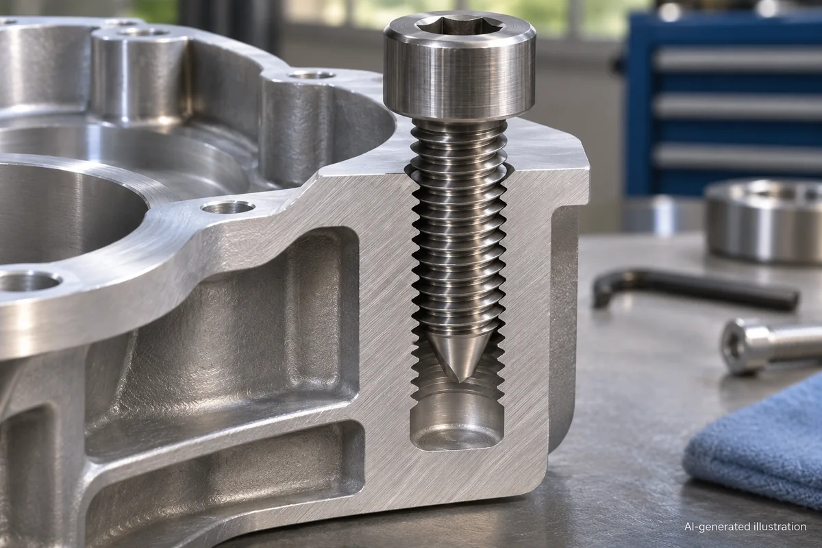
Use a section view where the distinction matters. Identify the reference face for every depth, including any counterbore or recess. If a drill makes a pointed bottom, its tip reaches deeper than the full-diameter cylindrical portion. Neither of those depths automatically establishes the length of usable full-form thread.
| Quantity | What to define | Why it matters |
|---|---|---|
| Usable full-form thread | Thread designation, tolerance class, reference face and required usable length | Incomplete threads at the entry or bottom may not provide the specified engagement |
| Full-diameter drilled depth | The cylindrical hole length and its depth reference | The tapping route needs room beyond the required complete threads |
| Maximum bottom extent | Permitted deepest cut and minimum remaining wall | A deeper drill tip can approach a cavity or sealing surface |
| Installed screw penetration | Fastener length, joint stack and tolerances | The screw must clamp the joint while retaining the required engagement and bottom clearance |
Leave room for the actual tap and chip path
A cutting tap’s lead contains progressively formed teeth. The tool therefore needs a runout allowance beyond the required complete thread. A shorter lead can help in limited space, but it also changes the cutting conditions. SFS explains the tradeoff between lead chamfer length and cutting-edge load, and distinguishes tap designs for blind and through holes. See SFS’s thread-generation guidance.
Do not treat a “bottoming” tool description as permission to cut directly into the drilled floor. Ask for the selected tool’s lead geometry, usable reach and required clearance. Confirm whether the program’s depth reference concerns the tool tip or the point that produces complete threads. The available space must also suit the actual chip-removal strategy.
Sandvik Coromant identifies component material, hole type, drill selection and coolant supply as important tapping choices. Its guidance connects coolant delivery with chip evacuation, thread quality and tool life. That supports reviewing the complete setup rather than prescribing one clearance for every hole. See Sandvik’s tapping operation tips. Cutting parameters and fluid selection belong to the approved tool and machine procedure.
Check screw engagement and bottom clearance together
Check the longest permitted screw penetration against the earliest permitted bottom obstruction, including incomplete threads that can stop the screw. Include the actual screw-length tolerance, counterbore, cover thickness, washers and other stack elements. Separately evaluate the minimum engagement at the opposite limits. A combination that avoids bottoming can still leave too little engagement.
For a housing with a nearby internal cavity, the maximum drilled extent and remaining wall also need their own check. Increasing hole depth to solve assembly trouble can create a different problem. Required engagement, joint strength and wall thickness must come from the design review; a generic multiple of screw diameter is not a substitute.
Separate depth acceptance from thread-size acceptance
Agree how the required usable thread depth will be verified, including the gauge’s geometry and depth reference. A normal thread-size acceptance check does not, by itself, document every depth in the section view. Use the thread inspection guide to define the size and gauging scope separately.
Retain an identified trial part and its measurements. Where the hole is inaccessible, agree an appropriate verification method before production rather than promising that an ordinary depth probe will reach every surface. Check cleanliness and entry edges too: a burr or trapped debris can complicate an assembly trial. The burr-control guide covers the need to define functional edges and inspection access.
Drawing and first-part review checklist
- Specify thread designation, tolerance class and usable full-form depth.
- Identify the depth reference face and any entry chamfer or counterbore.
- Define the maximum drilled extent and remaining-wall requirement.
- Review minimum engagement and bottom clearance across the assembly tolerances.
- Resolve tool lead, chip-removal and access assumptions with the machining team.
- Agree depth verification, thread gauging, cleaning and first-part approval evidence.
For related component geometry, see the machined battery housing example. Send the drawing, fastener information and assembly stack to tonyzhou@lxcet.com for a part-specific review. Use the quality inspection information to start the discussion of required records; the feasible manufacturing and inspection scope needs confirmation for the actual part.