

Blog

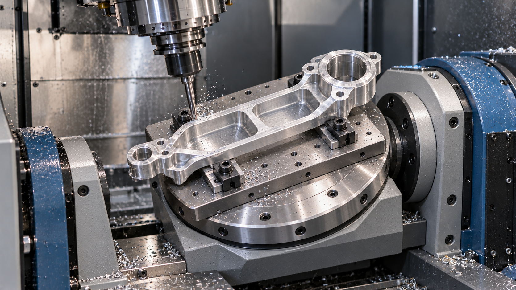
A thin aluminum enclosure looks correct while it is clamped, but the mounting face moves after release. A lightweight drone bracket fits one assembly and binds in the next. In thin-wall CNC machining, the useful result is a part that meets its functional requirements in the agreed inspection condition—not simply a good measurement inside the fixture.
What is the actual problem: chatter, deflection or distortion?
Start with an evidence log. Record when the problem appears, where it is measured and whether it follows the same region on successive parts. These distinctions help the engineering team choose a useful trial rather than making several uncontrolled changes at once.
| Observed symptom | Question to investigate | Useful first check |
|---|---|---|
| Repeating marks or an unstable finish | Is cutting vibration occurring? | Review tool reach, support and the cutting strategy. |
| A feature changes when clamping is released | Is the fixture forcing the part into a different shape? | Compare measurements before and after release using the same datums. |
| Dimensions drift between inspection sessions | Are the measurement conditions consistent? | Record temperature, support, restraint and measurement method. |
| Part passes dimensional checks but will not assemble | Do the drawing controls describe the functional interface? | Review the mating component, datums and assembly condition. |
How to reduce vibration in thin-wall milling
Sandvik Coromant identifies workpiece support, stable clamping, tool length and machining strategy as important factors in milling stability. Support should oppose the cutting forces, and tool reach should be kept as short as the geometry allows. These principles are a starting point for process review; they do not establish a universal wall thickness or cutting parameter. Source: Sandvik Coromant milling application guide.
For the project review, mark the flexible regions on the model and ask which surfaces can support them without marking a cosmetic face. Identify pockets that require long cutters. Ask the supplier to explain the planned support at the operation where the wall is most flexible. A fixture that works during roughing may need a different arrangement during finishing.
Design choices that can make thin walls easier to machine
The following are engineering review options, not automatic design changes. The component owner must confirm that each option preserves strength, clearance, mass and assembly requirements.
- Retain local stiffness where possible: consider a rib, a thicker mounting region or a shorter unsupported span when the functional design permits it.
- Improve cutter access: review deep narrow pockets and internal corner radii. Ask for the tool-access constraint before approving a change.
- Distinguish functional surfaces: identify the sealing face, bearing interface or mounting pads that need close control, and separate them from noncritical surfaces.
- Agree on handling surfaces: define where the part may be located, supported or clamped so the process plan does not rely on an unsuitable face.
There is no single minimum wall thickness that applies to every CNC part. Wall height, material, local geometry, access and verification requirements all matter. Treat a supplier’s minimum-size guideline as a screening rule, then request a drawing-specific review.
A controlled plan for reducing aluminum part distortion
Use a sample trial with a written baseline. The goal is to determine which change improves the required result and whether that result remains repeatable.
- Define acceptance: identify the dimensions and geometric controls that govern assembly, plus the inspection restraint condition.
- Record the baseline: document material specification, drawing revision, operation sequence and measurement method.
- Choose one trial variable: for example, a support arrangement or finishing sequence proposed by the machinist. Avoid changing the fixture, program and inspection method together.
- Inspect after release: compare the critical features under the agreed condition. Record any difference between restrained and unrestrained results.
- Review repetition: confirm the finding on additional samples before releasing the agreed process for the order.
If material stress or heat treatment is suspected, obtain material and process information before specifying a remedy. Any stress-relief step must be compatible with the grade, temper, finish and functional requirements; it should not be added as a blanket instruction.
Thin-wall part inspection checklist
- Current drawing and model revision match.
- Critical datums and mating interfaces are clearly identified.
- Inspection support and any restraint are documented.
- Wall thickness, mounting-face geometry and relevant hole positions are checked.
- Edge breaks, burrs and visible surface requirements are reviewed.
- Post-finish measurements are included where the finish affects a functional interface.
- Nonconforming results lead to an agreed corrective action before quantity production.
What should you send for a manufacturability review?
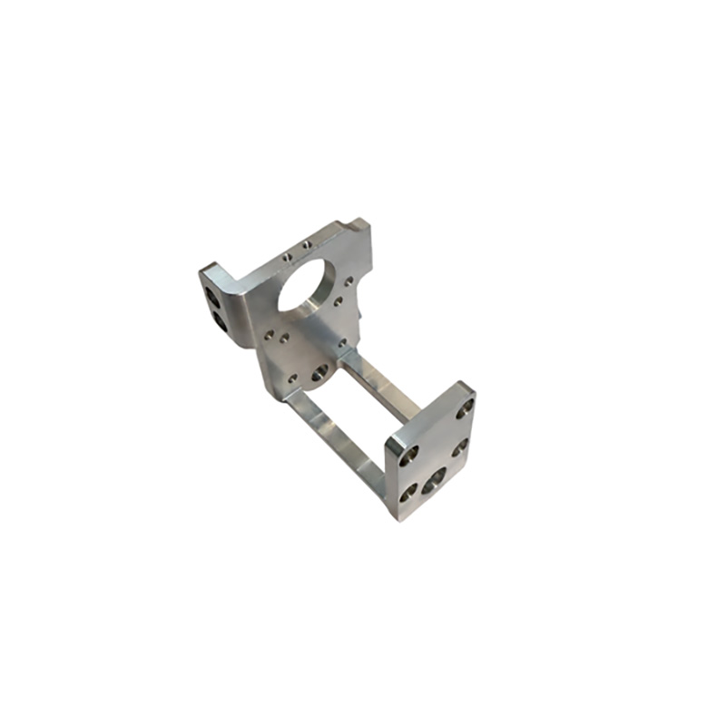
Provide the 3D model, dimensioned drawing, material grade and condition, quantity, finish, critical assembly interfaces and required inspection evidence. Include a mating-part sketch when it explains the functional requirement. For lightweight applications, compare the drone motor mount and equipment bracket examples, and see our CNC material selection guide.
Send your drawing to tonyzhou@lxcet.com to discuss the project. LXCET capability, achievable tolerances and inspection scope are confirmed against the actual drawing. This article provides a review framework, not a guaranteed process recipe.