

Blog

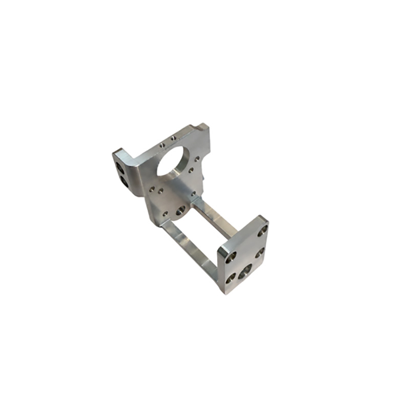
A welded machine bracket sits flat in its fixture, yet rocks on the mounting plate after release. Tightening the bolts pulls it down, but may load the assembly in a condition its designer never intended. Welding distortion control needs an acceptance plan for the finished, released part, not just a fixture that makes the work look straight.
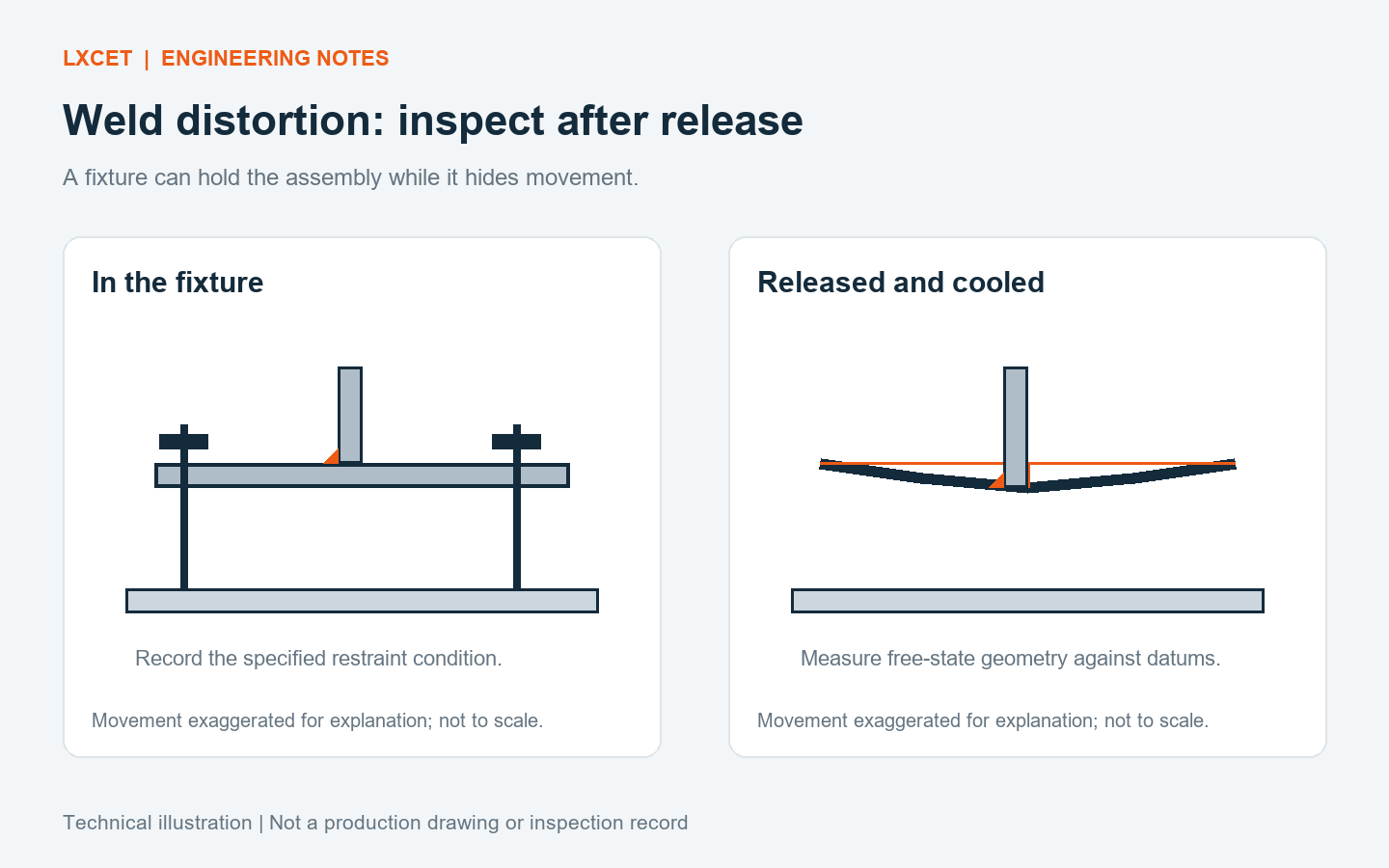
Why a bracket moves when the clamps come off
Welding creates uneven heating and cooling. Local expansion followed by contraction can leave permanent shape change and residual stress. Bowing, twisting and angular movement are different symptoms; record which one prevents fit before selecting a remedy. TWI explains these mechanisms in its overview of weld-material distortion.
A useful investigation starts with three observations: the assembly before welding, its condition while restrained, and its geometry after release at the agreed measurement temperature. Note the material grade, section thickness, joint preparation and weld sequence beside those results. Without that record, a change in fit-up can be mistaken for a successful process adjustment.
Review welding distortion control before adding stronger clamps
Restraint reduces movement during welding but does not remove the underlying shrinkage. TWI’s guidance on fixtures and restraint warns that locked-in stresses can cause movement after release and that excessive restraint can increase cracking risk. A fixture also needs a practical removal path for the completed assembly.
Ask the welding engineer to review the restraint method against the actual material and procedure. Pre-setting a part may be an option, but the amount is established with representative trials rather than guessed from a photograph. Do not treat stress relief as a universal repair: its suitability and its effect on material condition and dimensions require a separate review.
Make the weld do its specified job
More weld metal is not automatically better. TWI’s design guidance links distortion control to weld placement, deposited volume and balance around the assembly’s neutral axis. For a suitable joint, alternating work on opposing sides can help balance contraction. The qualified procedure and design requirements still control the actual sequence and weld size.
A designer may consider a formed section, a different joint arrangement or intermittent welding where the application permits. A fabricator should not substitute intermittent welds for a specified continuous seam: sealing, corrosion exposure, fatigue or structural requirements may rule that change out.
| Observed problem | Review with engineering | Evidence before release |
|---|---|---|
| Mounting plate bows after unclamping | Weld location, deposited volume, sequence and restraint | Free-state mounting-face measurements after cooling |
| A flange rotates out of square | Joint geometry, fit-up and angular shrinkage | Angle or position relative to the drawing datums |
| Assembly passes only when pulled down by bolts | Whether the specified acceptance condition permits that restraint | Defined fixture, supports and loading method if required |
| Parts vary between otherwise similar batches | Fit-up, tack pattern, sequence and material condition | Controlled trial records and measurements of representative parts |
| Distortion is followed by a request for straightening | Approved correction method and material restrictions | Reinspection plus any additional checks required by the procedure |
Plan machining and finishing around final acceptance
If the design includes precision mounting faces or locating bores, discuss whether they should be finished after welding. That route needs accessible features, enough machining allowance and a datum strategy that represents the finished assembly. It is a feasibility question, not a promise that every welded frame can be corrected by machining.
Keep dimensional acceptance separate from weld acceptance. A flat mounting face does not demonstrate weld integrity. Conversely, a satisfactory weld examination does not establish that hole locations meet the assembly drawing. Specify both types of evidence where the application needs them.
RFQ and acceptance checklist for welded assemblies
- Issue the assembly drawing, material grades, thicknesses and controlled revision.
- Identify functional mounting faces, locating features and applicable tolerances.
- State weld requirements and any applicable procedure, qualification or examination requirements.
- Define whether dimensions apply free-state or under a specified restraint.
- Ask for the proposed sequence, fixturing approach and post-weld operations.
- Agree the inspection stage, measurement conditions and report content.
- Require approval of geometry changes, straightening or other proposed corrective work.
- Review representative first-piece results before releasing the remaining quantity.
Send the interface that must work
Use the welding and assembly review and quality inspection information to prepare your enquiry. For a machine frame or robotics bracket, mark the mating faces and include the assembly model. Send the package to tonyzhou@lxcet.com or use the drawing enquiry form. Route availability and acceptance requirements need project-specific confirmation.