

Blog

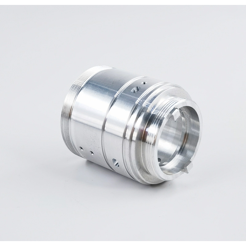
A turned bore looks acceptable at the entrance, but the deeper section has repeating marks and the mating component will not seat consistently. Changing the diameter offset alone does not identify the cause. CNC boring chatter should trigger a structured review of tool reach, workholding, cutting conditions and the evidence used to accept the bore.
First separate the symptom from the acceptance requirement
Record where the problem begins: at entry, near a shoulder, after a specific depth or during a particular operation. Retain the rejected part and its machining record. Repeating surface marks may suggest vibration, but appearance alone cannot establish the mechanism. Ask whether the feature also has diameter variation, taper, poor roundness or a failed surface-texture result.
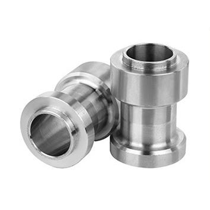
A connector shell, sleeve or robot-joint housing can contain several different interfaces. Identify the actual bearing, seal, thread or locating surface before selecting a remedy. An attractive outer finish is not evidence that the internal fit meets the drawing.
Review boring bar overhang before changing the program
Sandvik Coromant’s current turning guidance identifies damped tooling as an option for internal turning with long overhangs. That makes tool reach a useful review point, but a supplier’s advertised tool range is not a guaranteed part tolerance. Check the installed bar, holder and clamping arrangement against the tool maker’s instructions. Source: Sandvik Coromant, Silent Tools for turning.
Record unsupported tool length and bar diameter separately. Illustrative setup comparison: an 80 mm unsupported length with a 16 mm bar gives L/D = 5; reducing the length to 64 mm gives L/D = 4. This calculation describes geometry only. Neither ratio proves that a particular material, insert or machine will produce an acceptable bore.
CNC boring chatter troubleshooting: a practical decision table
| Observation | Question to investigate | Evidence to retain |
|---|---|---|
| Marks become worse deeper in the bore | Can reach be shortened, or does the setup require a different bar or support arrangement? | Actual reach, bar diameter, tool identification and measured results at several depths. |
| Results change after reclamping | Are locating surfaces clean and is the agreed clamping method repeatable? | Fixture setup, part orientation and before/after measurements in the specified condition. |
| Damage appears near a shoulder | Is there adequate tool clearance and a suitable entry or exit strategy? | Feature location, toolpath review and an identified trial part. |
| Changing an offset fixes size but leaves marks | Has the underlying surface or form problem been evaluated separately? | Size, form and surface-texture results against their individual requirements. |
| A new insert changes the result | Do edge condition, insert selection and replacement controls explain the difference? | Insert identification, cutting conditions and traceable trial results. |
Choose cutting geometry for the actual boring operation
Sandvik’s boring application guide discusses positive cutting geometry and a small nose radius as measures to reduce vibration tendency. Treat these as options to evaluate with the tooling supplier, not universal settings. Document the proposed change and check its effect on the required surface and geometry. Source: Sandvik Coromant, Boring application guide.
A controlled trial needs an unchanged drawing revision, known material condition and clearly recorded baseline. Change the selected parameter, inspect the resulting part and compare it with the baseline. Avoid changing speed, feed, tool, clamp method and offsets together: the improvement would then be difficult to reproduce or explain.
Verify bore surface finish and geometry after the trial
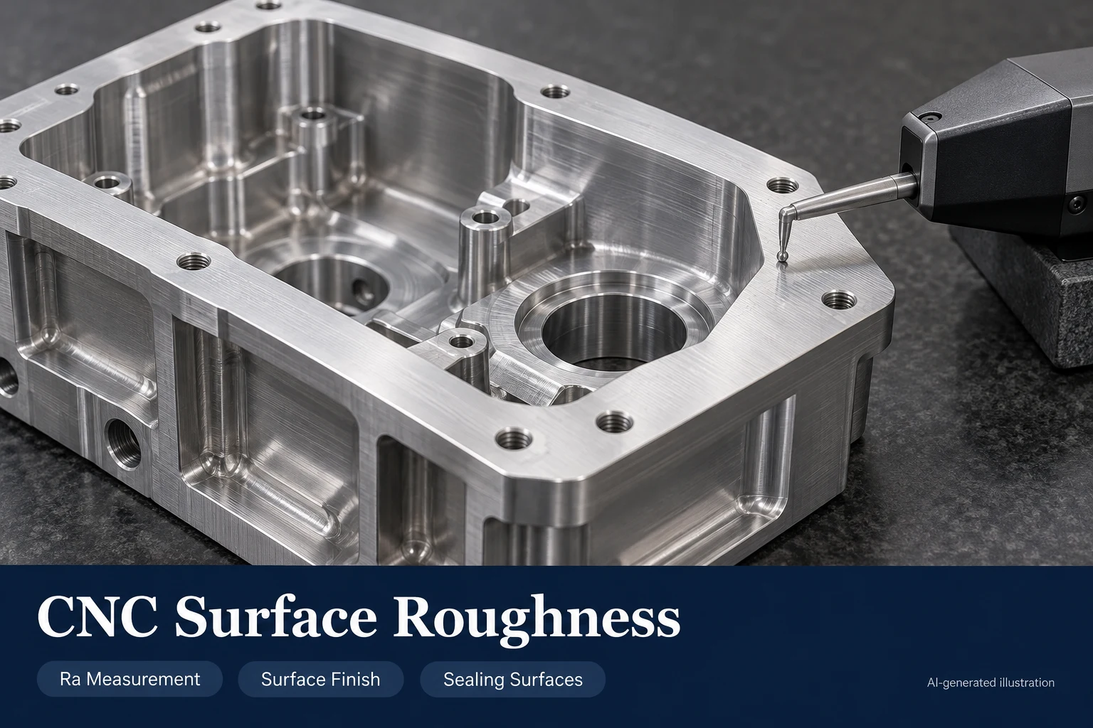
For a functional precision bore, define what must be inspected and where. A diameter reading near the opening may leave the deeper region unevaluated. The inspection method must reach the relevant feature and be suitable for the tolerance. Surface texture, roundness and position are separate requirements when the drawing calls them out.
- Confirm the drawing revision, material and final surface condition.
- Identify the functional bore length and the required measurement locations.
- Record measured values with the applicable limits and units.
- Agree on the datum setup and any clamped or free-state inspection condition.
- Check the mating component where an assembly trial is part of approval.
- Retain the approved setup and define what requires another review.
What should an engineer include in a precision bore machining RFQ?
Send CAD and a controlled drawing with bore depth, tolerances, datum relationships, surface texture and finish. Include the mating-part requirements and access restrictions. Ask the supplier to flag unresolved inspection or tooling assumptions before the quotation becomes a production commitment.
Discuss the bore before approving the route
See our machined connector shell example, manufacturing solutions and inspection report checklist. Send your drawing and the functional requirements to tonyzhou@lxcet.com for a part-specific feasibility review.