

Blog

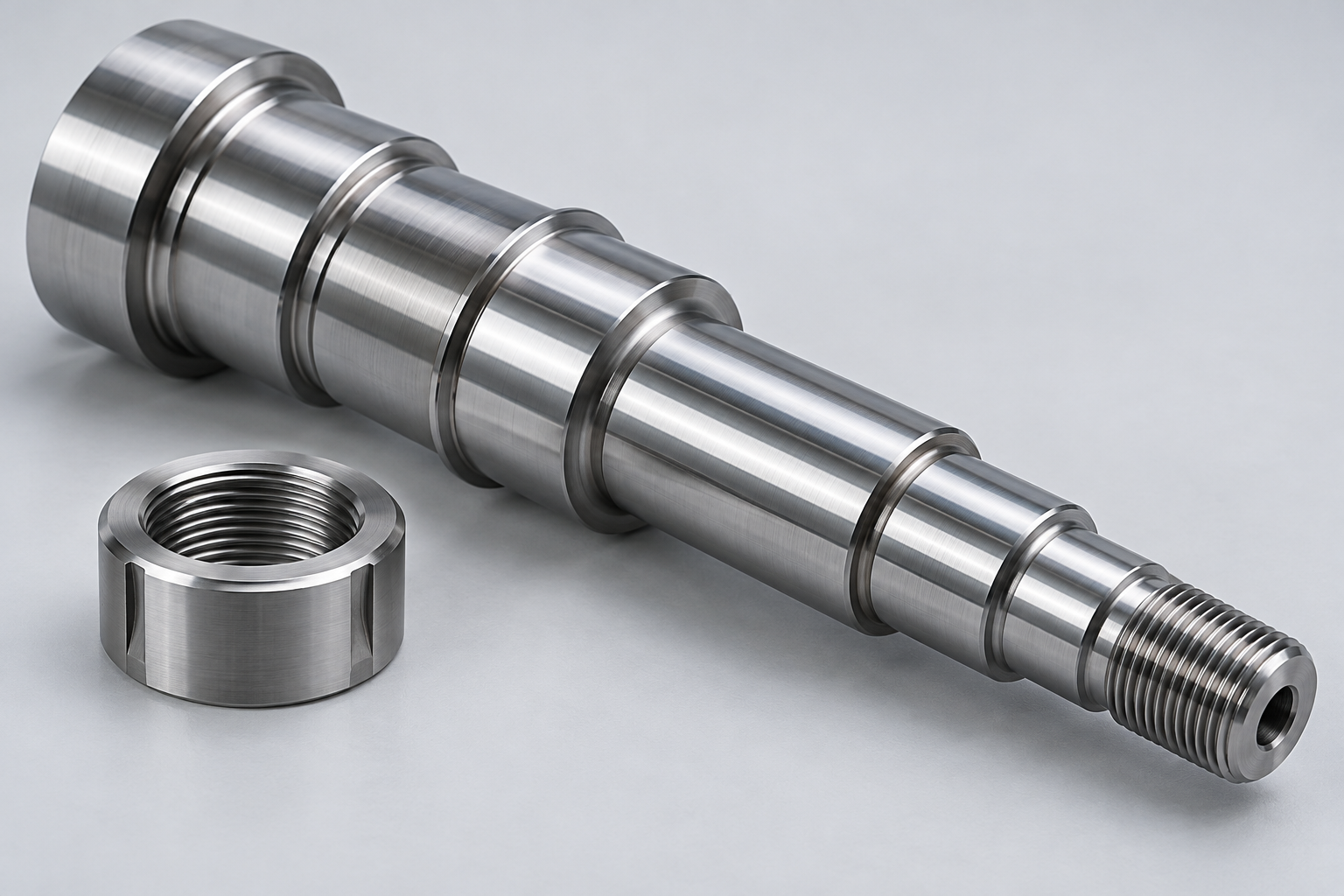
A turned shaft can meet its diameter tolerance and still fail during assembly. A burr on a shoulder, thread start or cross-hole may scratch a mating component, damage a seal or prevent the part from seating. Burr control in CNC turning should therefore start with the drawing and machining sequence, rather than a final instruction to “deburr all edges.”
Why do burrs on turned parts become assembly problems?
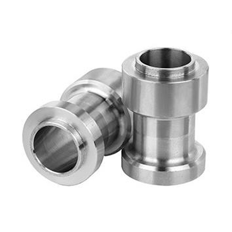
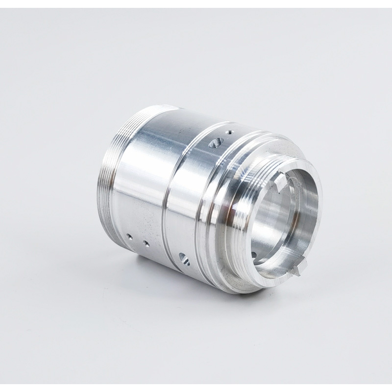
The important question is where the displaced material sits relative to the part’s function. An external sharp edge is different from a loose fragment inside a fluid passage. A small burr at a locating shoulder can create a false contact point; a thread-entry burr can affect engagement; an inaccessible cross-hole burr may remain after an external visual inspection.
Separate three requirements in the drawing review: the size of the parent feature, the intended edge geometry, and cleanliness. A dimensionally acceptable bore does not, by itself, establish that its internal intersection is free of loose material.
Match the burr location to a controlled solution
| Location / symptom | Process question | Verification after finishing |
|---|---|---|
| Part-off face or center pip | Review insert geometry, center height, overhang and the cutoff sequence. | Check remaining projection, face flatness and usable contact area. |
| Shoulder next to a bearing seat | Can a programmed edge operation reach the edge without changing the functional land? | Confirm edge geometry and the remaining seating length. |
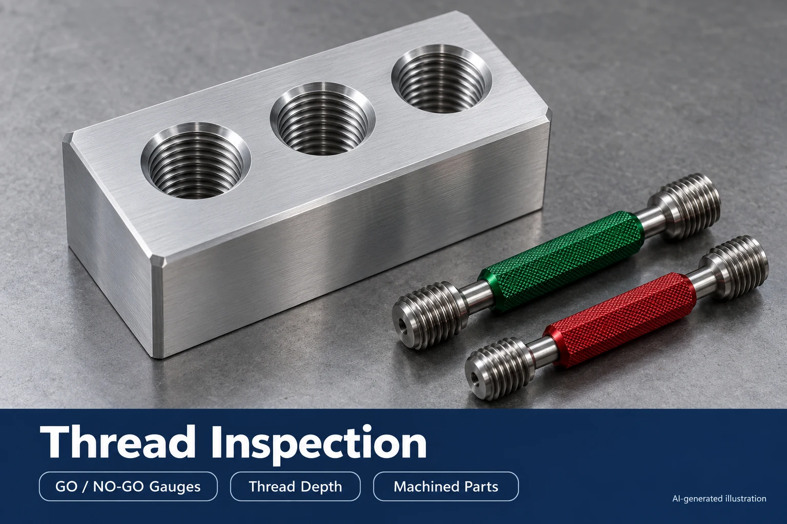
| Thread start or runout | Review the entry, relief and deburring sequence; protect the thread profile. | Check engagement with the specified gauge and inspect the entry separately. |
| Cross-hole / bore intersection | Plan tool access and a suitable internal deburring method before production. | Use a defined inspection view or access method and check cleanliness. |
| Burrs increasing through the batch | Review tool condition, chip evacuation and changes to the setup. | Compare edge condition at agreed process checkpoints. |
Reduce parting-off burrs without creating a new defect
Sandvik Coromant’s parting guidance links pip and burr behavior to cutting geometry and setup stability. It describes sharper geometries and small corner radii as options, but also explains that front-angled inserts introduce side forces and can compromise flatness, chip control or stability. The appropriate choice depends on the actual operation. Source: Sandvik Coromant, Parting off.
Use that guidance as a structured trial, not a universal cutting recipe. Record the material condition, tool and geometry, overhang, coolant arrangement and cutting parameters. Change one relevant variable, inspect the edge and neighboring features, then decide whether the result is acceptable. A smaller pip is not a success if the cutoff face no longer meets its requirement.
Write a measurable deburring specification
Identify edges that must remain sharp, edges that need a controlled break, and intersections where loose material is unacceptable. Specify the inspection method and acceptance limits where failure would affect function. Avoid applying a large general edge break to every feature, especially thin walls, sealing lands and short seating shoulders.
Drawing example only: if a designer specifies an edge break of 0.20 ± 0.05 mm, the resulting allowed range is 0.15–0.25 mm. That example is not a recommended value for every part or an LXCET capability claim. The designer must choose the requirement from the interface geometry, assembly and service conditions.
Choose the deburring method around the functional surface
Programmed chamfering can make accessible edges more repeatable, while controlled manual operations can be useful for low-volume or difficult-to-access features. Brush or abrasive processes require attention to adjacent surfaces, trapped media and dimensional change. An internal intersection may need a dedicated approach. Review accessibility, material response, cleanliness and inspection before approving a method.
Do not use thread gauging as a substitute for checking every edge, and do not treat a clean photograph as proof of internal cleanliness. Agree on what must be inspected, how it will be viewed or measured, and what evidence will accompany the parts.
Acceptance checklist for turned-part burr control
- Mark critical edges and protected surfaces on the controlled drawing.
- Define required chamfers, radii, edge breaks and any sharp-edge exceptions.
- Confirm that burr removal preserves fit diameters, seating lengths and thread geometry.
- Identify internal intersections and agree how they will be inspected.
- Specify cleaning, handling and packaging appropriate to the application.
- Review the first approved sample and define checks after tool or process changes.
Discuss the edge requirement with the part drawing
For an LXCET manufacturing review, send CAD, the controlled drawing, material, quantity and the assembly problem to tonyzhou@lxcet.com. Process feasibility and acceptance requirements are confirmed for the specific project. See our quality and inspection guide and CNC machining RFQ checklist for the information to include.