

Blog

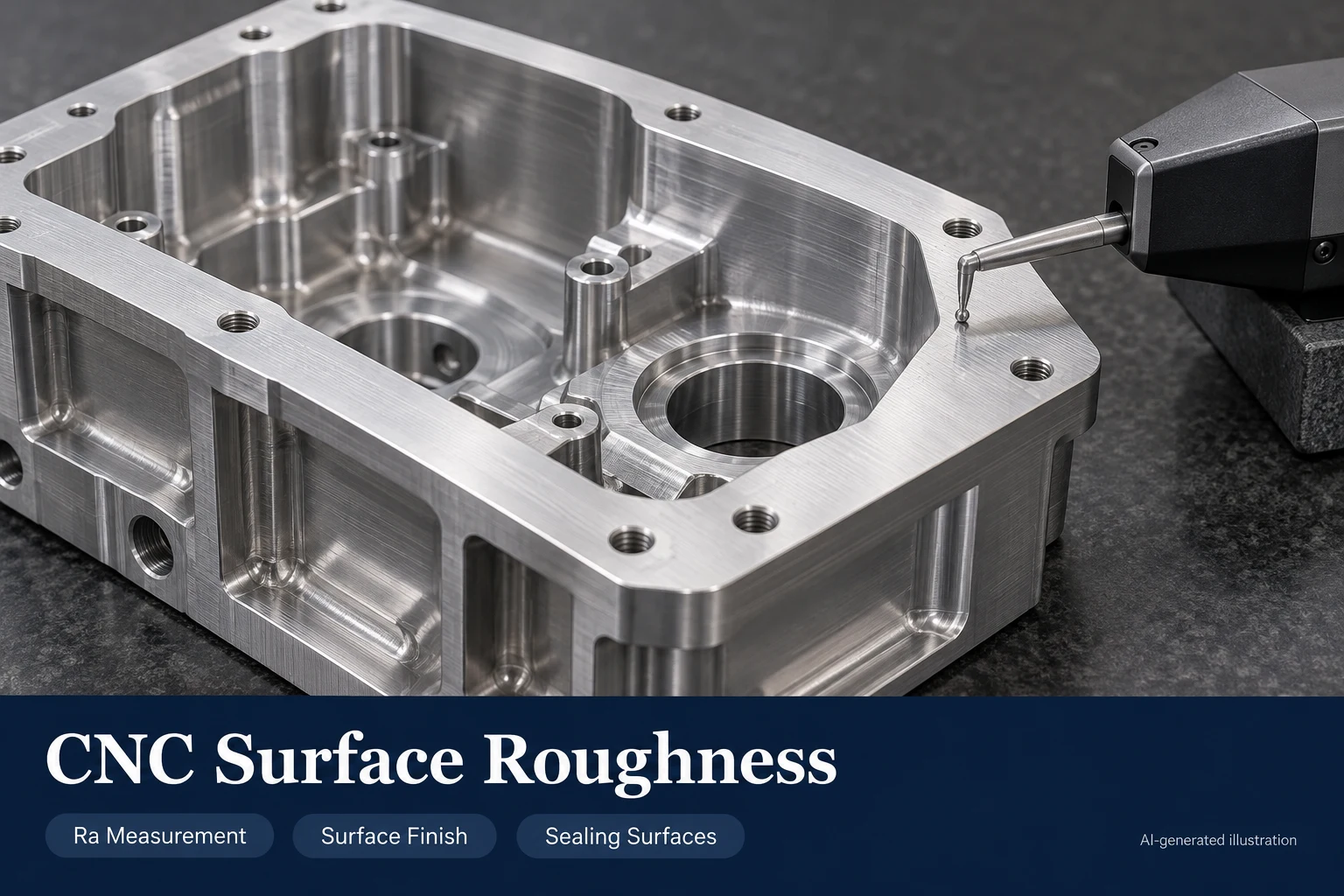
A machined face can look smooth and still be unsuitable for its job. A sealing face may have a scratch across the contact path. A shaft may meet its diameter tolerance but have a texture that causes premature seal wear. Specifying a lower roughness value everywhere can add finishing and inspection work without addressing either problem.
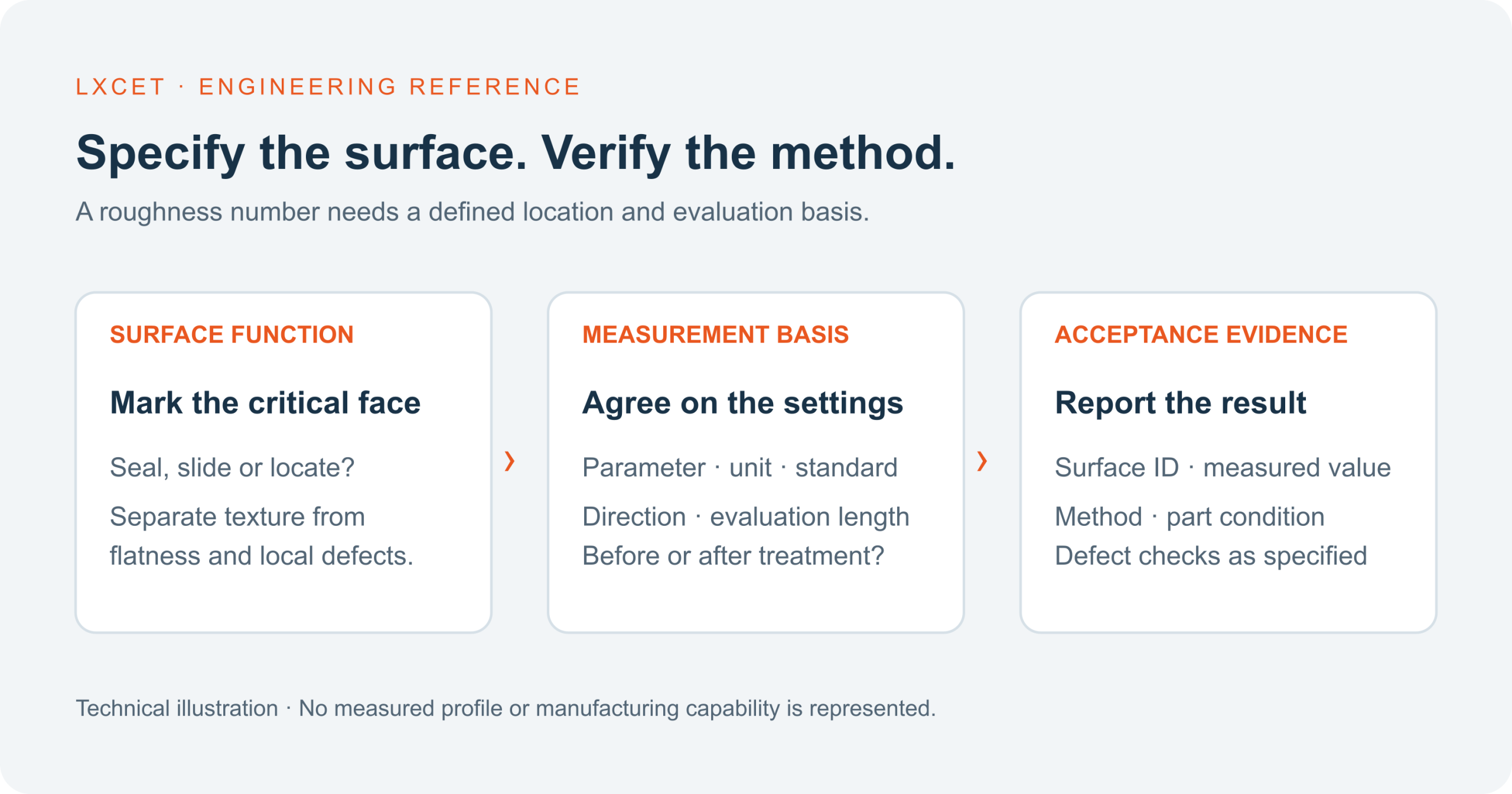
Surface roughness in CNC machining should be specified for the surface’s function and checked using an agreed measurement method. Start with the contact, motion or sealing requirement, then define the parameter, limit, measurement location and condition of the part at acceptance.
What Ra tells you, and what it leaves out
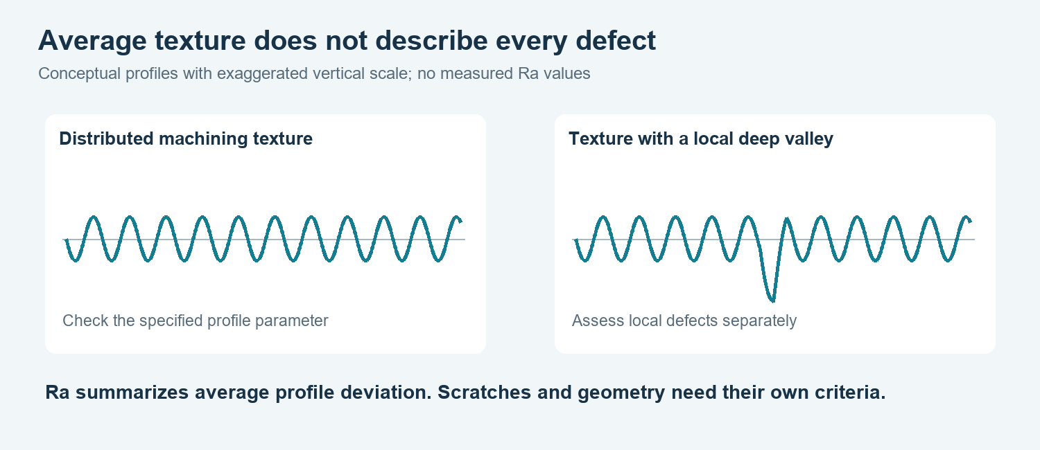
Ra describes the arithmetic mean of the absolute profile deviations from the mean line over the evaluated length. It is useful for specifying average texture, but it does not describe the entire surface. Different distributions of peaks and valleys can produce similar Ra values. A single scratch, burr or local defect can therefore need its own acceptance rule. Mitutoyo’s surface roughness measurement guide explains the distinction between average roughness and other profile parameters.
Do not convert Ra to Rz using a fixed multiplier for acceptance. The relationship depends on the actual profile and the definitions used. If the drawing requires Rz, measure and report Rz under the specified standard rather than substituting an estimated value.
Surface texture is also separate from geometry. A low Ra value does not prove that a face is flat, a bore is round or a shaft is straight. Keep the dimensional and geometric controls needed for assembly on the drawing.
Choose the requirement by surface function
The table below is a specification planning aid. It does not assign universal roughness limits; those should come from the design, mating-component requirements or application testing.
| Surface function | Question to resolve | Information to put on the drawing or inspection plan |
|---|---|---|
| Static sealing face | Can a local defect create a leakage path? | Texture requirement, flatness where needed, critical contact zone and scratch criteria |
| Shaft running against a seal | What texture and lay does the seal manufacturer require? | Applicable texture parameters, measurement direction, final diameter and finishing stage |
| Bearing seat | Which size and geometric characteristics control the fit? | Diameter limits, relevant form controls and the texture requirement for that specific seat |
| Non-contact housing face | Is the requirement functional or cosmetic? | A suitable general finish note, with separate visual criteria if appearance matters |
| Sliding contact | What does the lubrication and contact design require? | Relevant texture parameters and validation of the actual contact system |
Applying one very low Ra limit to every face makes quotation scope harder to control. Identify the few surfaces where texture changes performance. Give the remaining surfaces a separate, appropriate requirement.
Specify the standard before comparing results
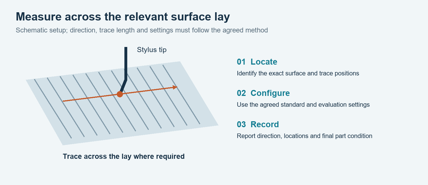
An inspection result needs more context than “Ra passed.” The drawing’s standard and evaluation settings determine how a measured profile becomes a reported value.
For new ISO-based specifications, review the ISO 21920 series: Part 1 covers indication, Part 2 covers parameters and Part 3 covers specification operators. Mahr explains this division in its guide to the updated surface-texture standards. Legacy drawings may still reference earlier standards. Resolve the applicable standard and edition with the customer rather than silently changing the evaluation method.
Agree on the parameter and unit, filtering or nesting settings, evaluation length, measurement direction and locations. Also establish whether acceptance applies before or after anodizing, plating, polishing or another treatment. Mahr’s calibration guidance describes changes in the newer evaluation framework; old and new instrument settings should not be assumed interchangeable.
If a narrow land or short bore cannot accommodate the required measurement path, resolve that limitation before machining. A shorter trace is not automatically an equivalent inspection. Record the approved alternative and its limits.
A practical specification example
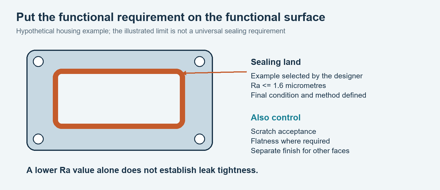
Consider a hypothetical aluminum housing with a static sealing land and several non-contact outside faces. The engineer has selected Ra ≤ 1.6 µm for the land after reviewing the seal design. This is an example requirement, not an LXCET capability claim or a recommendation for every seal.
The drawing should identify the land and state the relevant texture requirement. The inspection plan should identify the measurement locations, direction and evaluation settings under the agreed standard. Define scratch acceptance separately, and check flatness if the assembly requires it. If the part receives a finish, identify which condition must satisfy the limit.
For unit clarity, 1.6 µm is approximately 63 µin, using 1 µm = 39.3701 µin. Converting the unit does not change the parameter or authorize a different measurement procedure.
Diagnose a failed surface without removing critical material
Inspect the actual failure before choosing a finishing operation. Repeating the same measurement on a clean surface can help separate contamination from a genuine texture issue. Confirm that the stylus can reach the specified area and that the selected settings match the inspection plan.
If the measured profile shows repeated machining marks, review tool condition, feed strategy and process stability. If the problem is a local scratch, investigate handling, trapped chips and contact with fixtures. If the disagreement appears only after treatment, compare the same identified surface before and after that operation.
Do not polish a precision seat until the material-removal allowance and resulting geometry have been reviewed. A surface can become smoother while its diameter, edge condition or flatness moves outside the requirement. Related troubleshooting is covered in LXCET’s CNC boring chatter article.
Surface roughness inspection checklist
- Identify the drawing revision and the exact surface being accepted.
- Record the parameter, limit, unit, applicable standard and edition.
- Specify the measurement direction, locations and evaluation settings.
- Confirm access, cleanliness and a suitable, verified measurement setup.
- State whether the requirement applies before or after surface treatment.
- Report results against the locations inspected, including any agreed deviations from the method.
- Evaluate scratches, burrs and geometry against their own requirements.
For a quotation, send the drawing, material, quantity and finishing requirements, with critical surfaces clearly marked. Use LXCET’s Quality & Inspection page to discuss the required acceptance evidence, or contact tonyzhou@lxcet.com. Confirm measurement access and the proposed manufacturing route before committing to a finish requirement.