

Blog

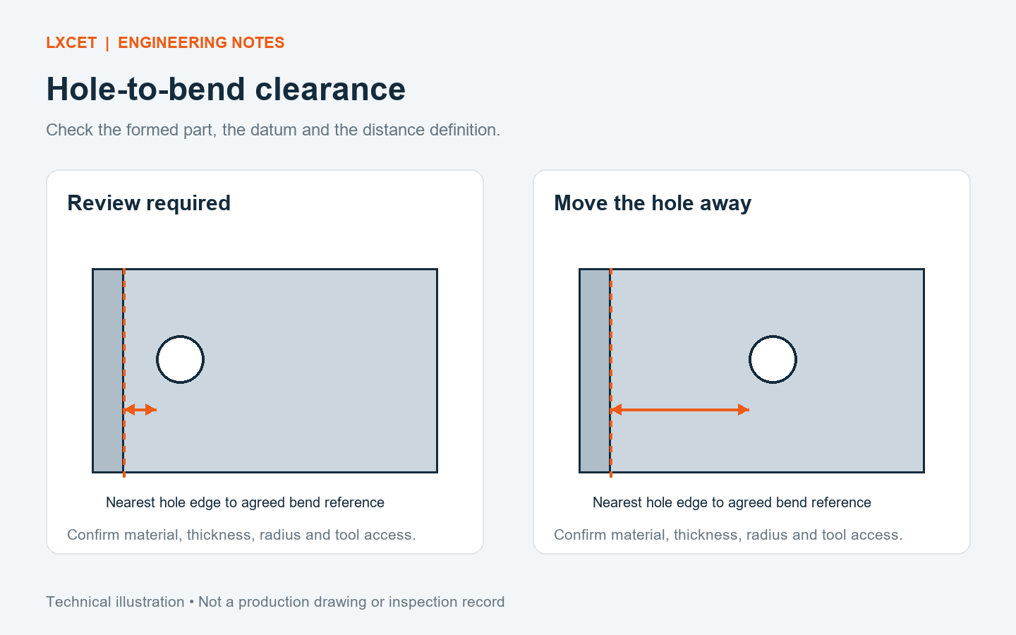
A bracket passes inspection as a flat blank, but its mounting hole becomes oval after bending. The screw no longer seats properly, or the assembled panel shifts when tightened. Sheet metal hole-to-bend distance needs to be reviewed in the formed configuration, together with the hole’s function and the datum used to locate it.
Why a correct flat hole can fail after forming
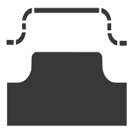
Bending changes the material around the bend. A nearby opening can change shape with it. Protolabs’ current sheet-metal toolkit makes feature clearance dependent on material, thickness and bend radius. Its material-specific guidance is a useful DFM reference, not a universal drawing standard or an LXCET capability guarantee. Source: Protolabs, placing features near bends.
Start by separating three questions: did the hole deform, did its location change relative to the assembly datum, or did the flange angle prevent alignment? Photograph the symptom, then measure the characteristic that the drawing actually controls. Enlarging a hole may make a screw pass while leaving a locating or sealing function unresolved.
Define sheet metal hole-to-bend distance before comparing numbers
Ask whether a quoted distance runs from the hole center or its nearest edge, and whether the bend reference is a tangent, an inside face or a flat-pattern bend line. These are different dimensions. A supplier should annotate the reference on the same drawing used for the feasibility review.
Illustrative geometry only: for a Ø6 mm hole, a 10 mm center-to-reference distance leaves 7 mm from the nearest hole edge to that same reference: 10 − 6/2 = 7 mm. This calculation does not establish a safe forming clearance. The result still needs review against the actual material, thickness, radius, tooling and direction of bending.
Do not freeze a flat pattern from an unexplained CAD default. Agree which document controls the final geometry and who validates the bend allowance against the selected route. Keep any supplier-proposed geometry change tied to a controlled revision.
Choose a fix around the hole’s function
| Situation | Route to review | Acceptance question |
|---|---|---|
| The hole has room to move | Increase clearance from the bend while checking the mating part. | Does the revised location still meet the assembly interface? |
| A fixed mounting pattern leaves little clearance | Review local relief or a revised flange arrangement with the fabricator. | Does the change preserve load path, sealing and required appearance? |
| A precise locating hole must remain close to the bend | Compare making or finishing that feature after forming. | Can the fixture and inspection method reference the finished datums? |
| The opening only provides loose cable access | Assess whether the expected deformation is acceptable. | Are edge condition, cable clearance and protection still adequate? |
| The part contains installed hardware | Review the hardware supplier’s hole, sheet and installation requirements. | Is seating and retention acceptable in the final configuration? |
These are design-review options, not automatic fixes. A relief may affect another requirement; a secondary operation adds a setup and needs access. Have engineering approve the selected trade-off before purchasing releases a revised order.
Inspect the formed bracket rather than only the blank
For a mounting bracket, identify the face that seats in the assembly and the feature that locates it. Check the hole in relation to those references after bending. If the drawing requires a particular clamped condition, state the fixture and loading method. Otherwise, a supplier and a buyer can obtain different results without either measurement describing the intended condition.
For an enclosure, repeat the fit check after the specified finish and hardware installation when those stages affect acceptance. A trial with an unfinished sample should not silently replace the requirements for the delivered configuration. Review visual brake marks separately from dimensional fit.
RFQ and first-piece checklist
- Send the formed CAD model and controlled drawing; identify any supplied flat pattern as controlled or reference-only.
- Specify material grade, condition, thickness and finish.
- Mark the hole’s function, finished size, location requirements and mating interface.
- Define the hole-to-bend distance reference and required bend geometry.
- Ask the supplier to identify any relief, tooling or secondary-operation assumption.
- Agree final datums, inspection condition and checks after finishing.
- Record the approved revision and disposition of the first-piece results.
Resolve the interface before placing the order
Review the sheet-metal process considerations, industrial machinery applications and inspection planning page. For an enquiry, send your drawing, quantities and assembly requirements to tonyzhou@lxcet.com. The available production route and acceptance scope require project-specific confirmation.