


Blog


Related posts
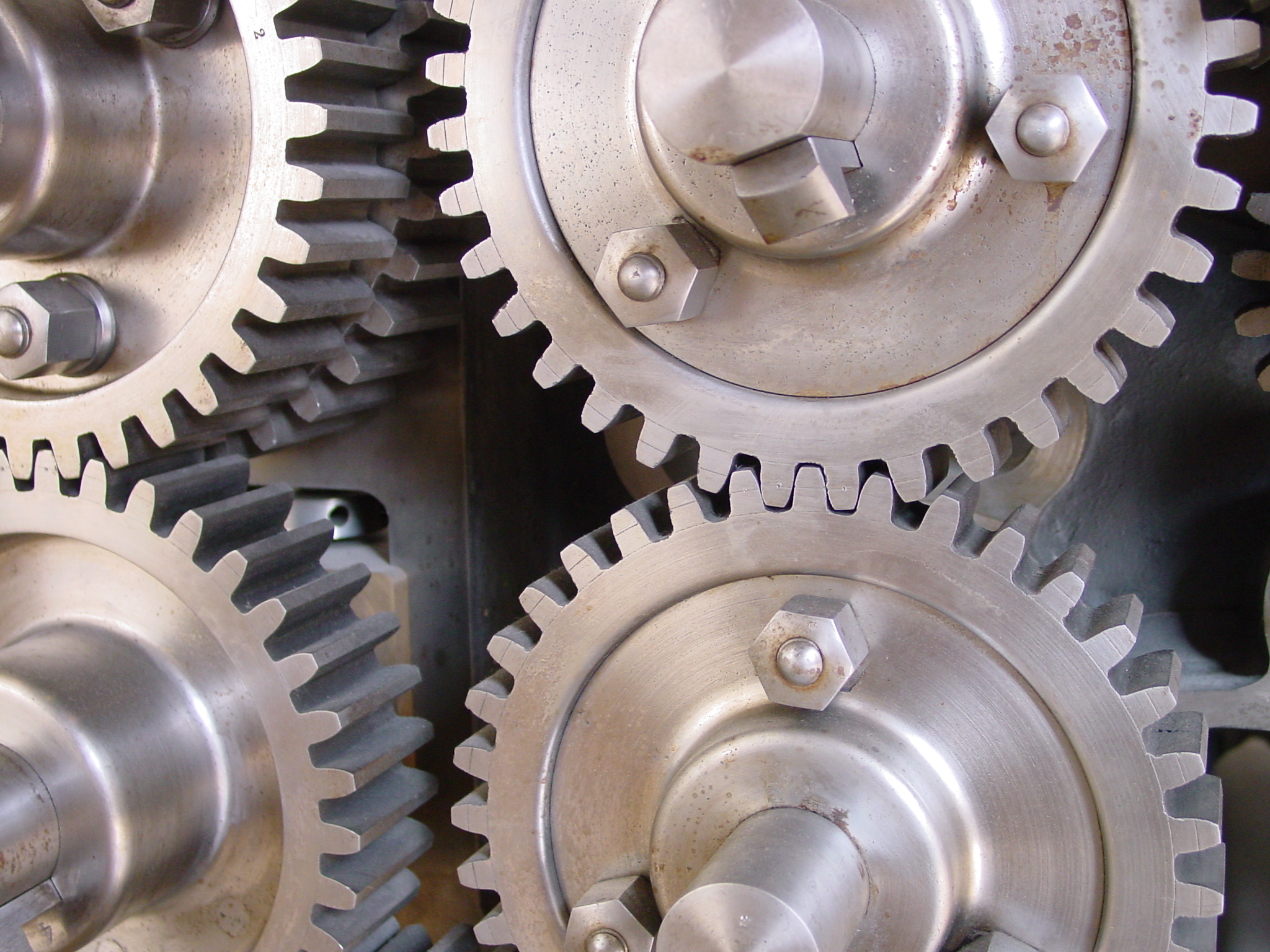
Gear Backlash: Check the Mounting Before Replacing the Gears

Gear backlash can change after a pair is installed even when the individual gears passed inspection. Before ordering replacement gears ...
Gear Machining RFQ: Define the Teeth Before Comparing Quotes
A gear machining RFQ that gives only outside diameter and tooth count leaves essential information unresolved. The supplier needs a def...
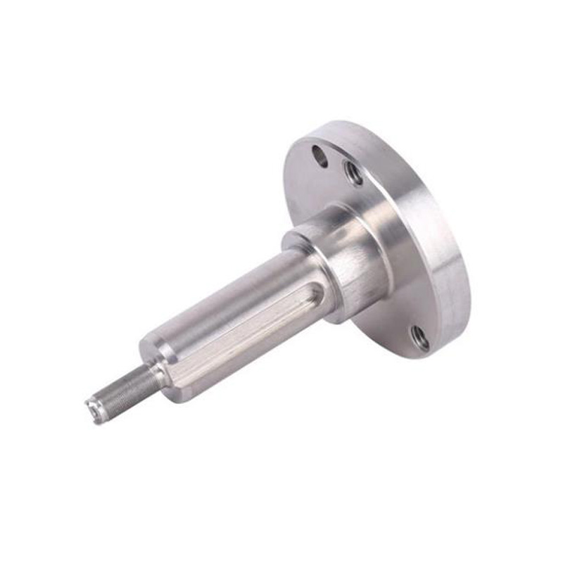
Heat Treatment Distortion: Plan the Final Machining Stage
Heat treatment distortion can leave a hardened shaft or gear blank outside its final geometric limits. Before finishing all surfaces to...
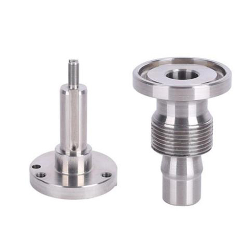
Electroplating Thickness: Specify the Final Fit Before Ordering
Electroplating thickness can turn a passing machined shaft into an oversized fit or reduce the clearance in a bore. State whether criti...

Cavity Machining: Review Chip Evacuation Before Finishing the Walls
A deep cavity can meet its depth requirement yet arrive with damaged walls or an uneven floor. In cavity machining, review chip evacuat...
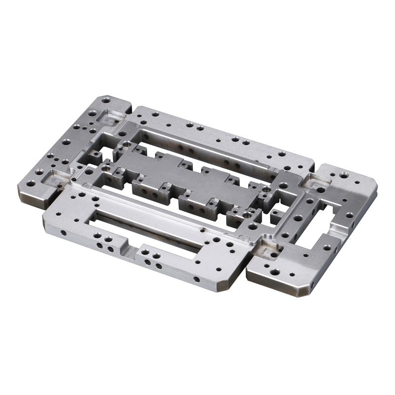
Partial Shipments of Machined Parts: Keep Release Records Together
Partial shipments of machined parts can keep an assembly line moving, but the first delivery is useful only if the right parts and acce...
Machined Parts Measurement Temperature: Resolve Conflicting Results
Machined parts measurement temperature can explain why a shaft passes the supplier's diameter check and fails at incoming inspection. B...
Customer-Supplied Material for CNC Machining: Agree the Handover
Customer-supplied material for CNC machining can create a dispute before the first finished part is delivered: the supplier receives fe...
Reaming Allowance: Check the Pre-Hole Before Chasing Size
A reamed hole that comes out undersize or with a poor finish does not automatically need another finishing pass. Check the pre-hole fir...
CNC Machining MOQ: Check the Constraint Before Ordering More
A CNC machining MOQ can reflect more than the number of parts a machine can produce. Before increasing an order to meet a supplier's mi...
Shaft Runout Inspection: Agree the Datum Before Accepting Results
A shaft can pass its diameter check and still wobble in an assembly. Before asking for a tighter machining tolerance, define which surf...
Shaft Shoulder Radius: Check Bearing Clearance Before Machining
A shaft diameter can meet its drawing tolerance while the bearing still stops short of the shoulder. Check the shaft shoulder radius ag...


