

Blog


A supplier sends threaded parts that accept the shop’s test bolt. At assembly, the customer’s fastener binds before reaching its intended position. The first question is whether both parties specified and inspected the same thread, in the same finished condition, using the same acceptance rules.
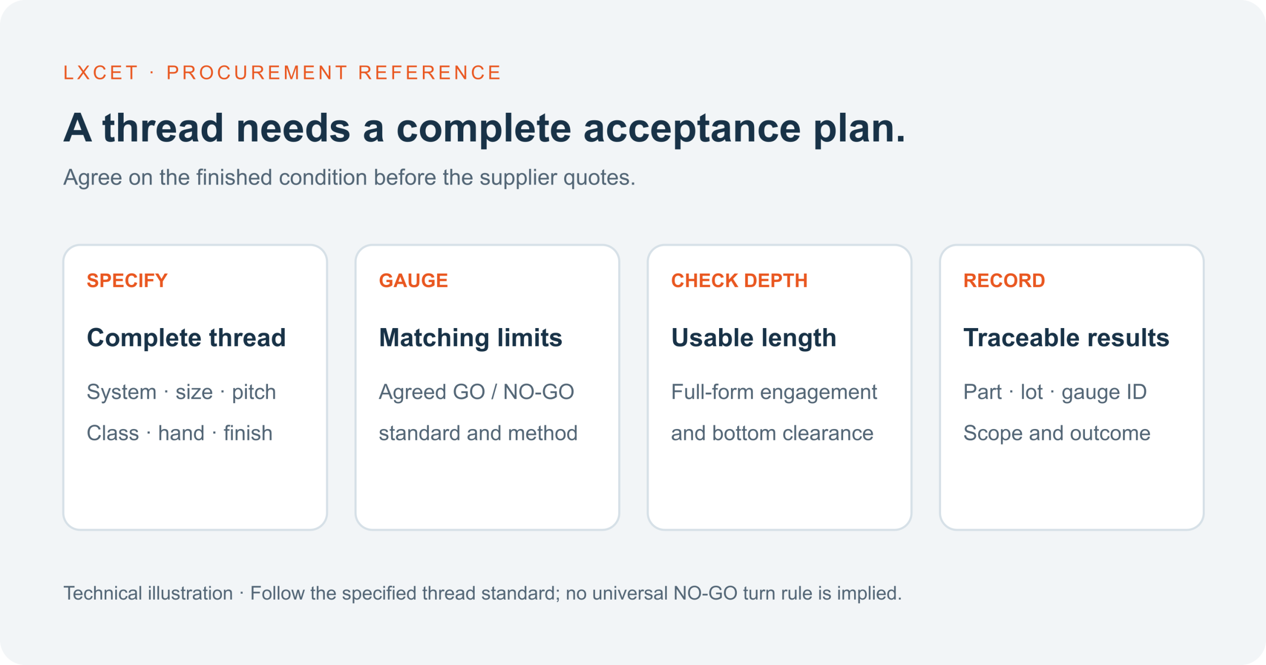
Thread inspection for machined parts needs more than a nominal diameter and a photograph of a gauge. Define the thread system, pitch, tolerance class, usable thread length, surface-treatment condition and applicable gauging standard before requesting a quotation. Then agree on the evidence needed to release the batch.
Put the complete thread requirement in the RFQ
“M10 threaded hole” leaves important decisions unresolved. As a hypothetical drawing example, M10 × 1.5–6H, right-hand, 15 mm minimum usable full-form thread depth communicates much more. It still needs the applicable standard, final surface condition and any entrance or bottom-clearance requirements. This example illustrates specification detail; it does not prescribe a thread for your design.
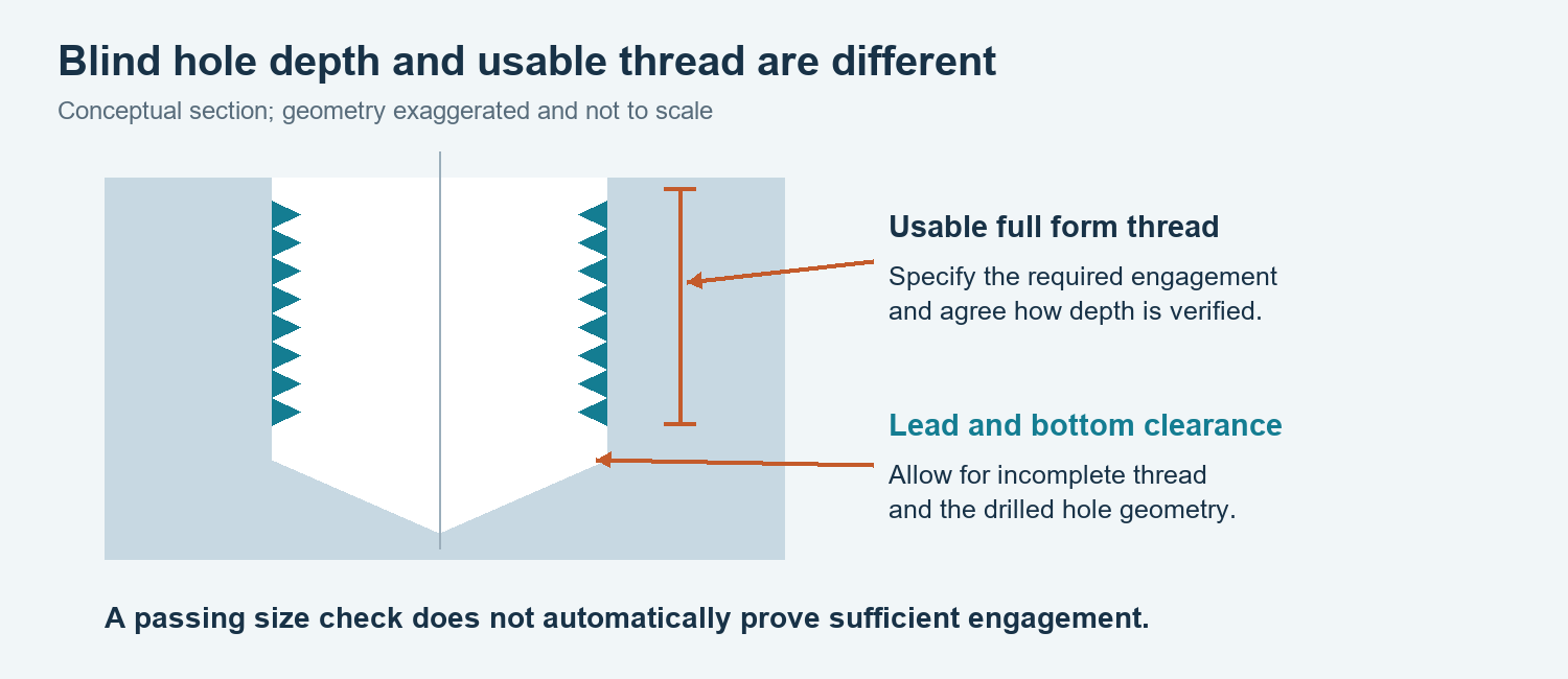
A blind hole’s drill depth and its usable full-form thread depth are different. The drill point, tap lead and bottom clearance can reduce available engagement. Show enough depth information for the supplier to plan the operation and for the inspector to verify the functional requirement.
| RFQ field | Detail to supply | Risk if omitted |
|---|---|---|
| Thread system | Metric, Unified or the specified pipe-thread system and standard | The supplier and buyer select different forms or rules |
| Size and pitch | Complete designation, including hand where relevant | A nominal diameter is mistaken for a complete specification |
| Tolerance class | The drawing’s internal or external thread class | Different acceptable limits are used |
| Usable engagement | Required full-form length or depth | A part starts correctly but cannot provide the intended engagement |
| Finished condition | Requirement before or after coating or treatment | Pre-treatment approval is mistaken for final acceptance |
| Inspection scope | Gauging standard, depth check, sampling and records | Quotations include different verification work |
Suppliers should flag uncertainty before making the part. Record the resolution in the drawing or purchase specification rather than relying on an informal assumption.
What GO/NO-GO thread gauges establish
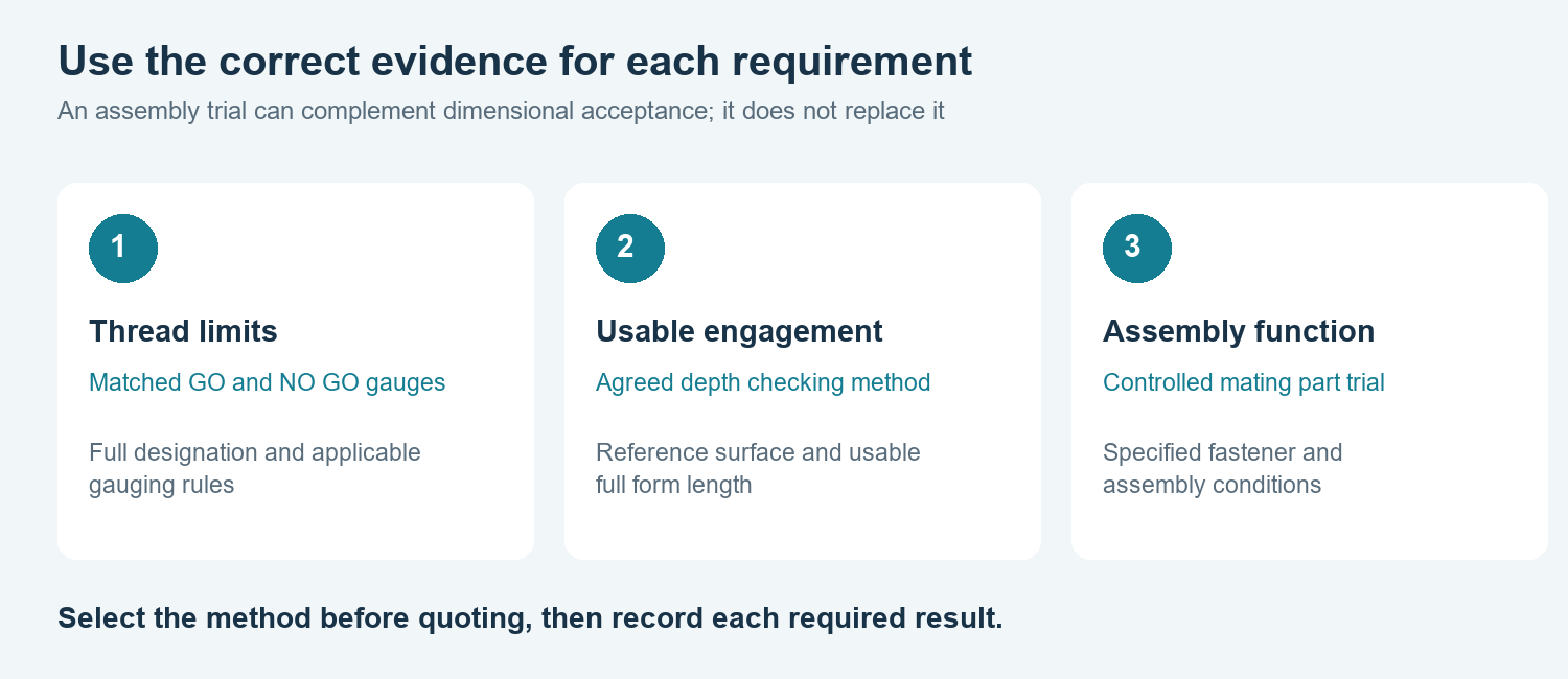
Matched thread gauges evaluate the specified thread limits under the applicable gauging rules. They are not a substitute for every requirement on the part. Thread location, usable engagement and other separately specified dimensions may need additional checks.
Select a gauge that matches the complete designation and governing system. For example, OSG lists a 7/8–14 UNF Class 2B thread limit gauge as a specific product; that designation matters, rather than merely choosing a gauge for the same nominal diameter.
Do not apply one universal NO-GO turn rule to every thread. The relevant standard, thread type and part configuration govern acceptance. Record that basis in the inspection plan. The gauge manufacturer’s inspection guide distinguishes thread-limit gauging from plain-diameter checks and other inspection tasks.
An ordinary bolt is useful for an agreed assembly trial, but it is not automatically a calibrated acceptance gauge. Its condition and actual size may not establish the drawing limits. Keep functional assembly testing and dimensional acceptance clearly identified in the report.
Inspect the finished thread, including usable depth
For blind holes, confirm that the method can distinguish sufficient usable thread from bottoming out. A mark on a gauge handle can be misleading if its reference point has not been related to the workpiece surface and the gauge’s geometry. Use an appropriate, agreed depth-checking method.
Check for chips, burrs and damage before interpreting a tight result. Clean the part and gauge using the approved handling procedure. Do not force the gauge through a restriction: forcing can damage the surfaces and obscure the cause of the failure.
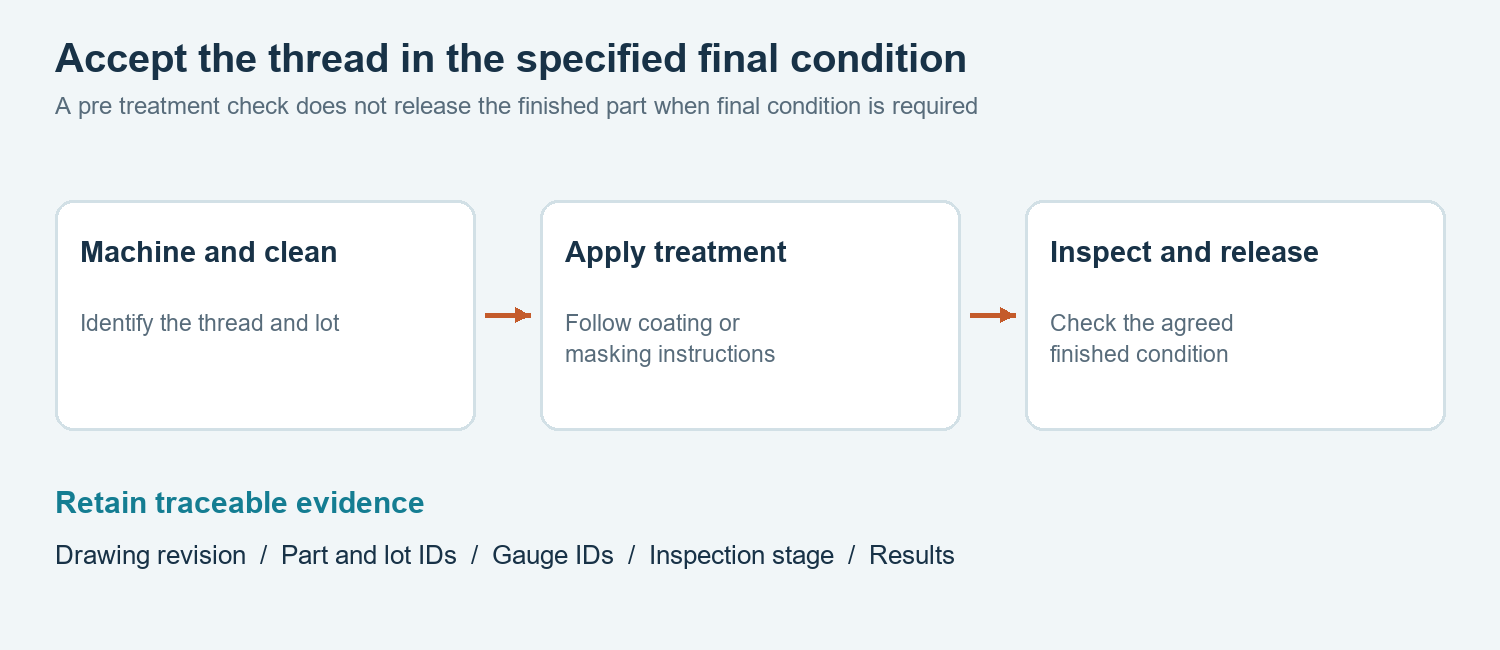
Where plating, anodizing or another treatment can affect the thread, state whether the final requirement applies after treatment and whether masking is required. Do not assume that a passing check on an unfinished part releases the finished component. LXCET’s anodizing dimensional-change guide explains why the process stage belongs in an acceptance plan.
Resolve supplier–customer disagreements methodically
First compare the drawing revision, thread designation, gauge markings and governing standard. Then compare the condition of the part at each inspection. A coated part and an uncoated sample do not necessarily represent the same condition.
Next review gauge identification, calibration status, cleanliness and visible damage. Compare the same identified parts under the agreed method. If disagreement remains, define a controlled comparison or independent measurement that addresses the disputed characteristic. Reworking the whole batch before establishing the cause can create a second problem and destroy useful evidence.
| Observation | Checks to make before rework | Evidence to retain |
|---|---|---|
| GO result differs between locations | Correct designation, gauge condition, cleanliness and inspection stage | Gauge IDs, part IDs and method used |
| Assembly stops short | Usable engagement, fastener length, bottom clearance and trapped debris | Depth results and the controlled assembly setup |
| Thread passes before treatment only | Final-condition requirement and treatment or masking instructions | Identified before/after results |
| Batch results vary | Tool condition, process sequence and which features actually failed | Results linked to the production lot and inspection sequence |
Build an acceptance record that purchasing can use
The purchase order should say what must be supplied, not simply request a “quality report.” A practical thread inspection record identifies the drawing and revision, part and lot, full thread designation, gauge identification, applicable procedure, inspection stage, quantity inspected and results.
If usable depth, thread location or an assembly trial is required, give each its own result. Record any approved concession and the person or function authorized to approve it. A photograph of a GO gauge in one hole does not describe the acceptance status of every threaded feature in a shipment.
The sampling plan should reflect the customer’s requirements, feature risk and process evidence. Do not describe sample inspection as 100% verification. If all threads must be inspected, make that scope explicit before the supplier quotes.
Before placing the order
- Release the complete thread designation and current drawing revision.
- Define minimum usable engagement and any required clearances.
- Identify the final surface condition and masking requirements.
- Agree on the gauging standard, depth-check method and inspection extent.
- Include gauge procurement and required reports in the quotation scope.
- Define how disagreements, concessions and rework will be handled.
Send these requirements with the drawing and order quantity to tonyzhou@lxcet.com, or use LXCET’s contact page. For broader batch records, see the CNC inspection report checklist. Confirm the proposed inspection scope before ordering, so engineering and purchasing approve the same acceptance conditions.