

Blog


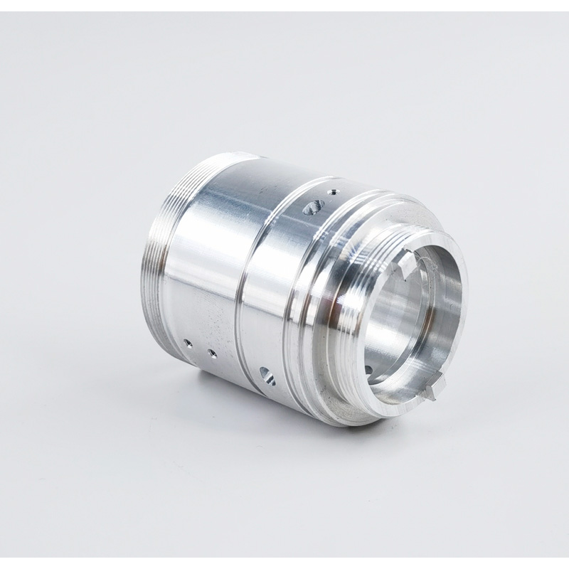
A shaft and housing fit correctly before finishing, but the same assembly binds after anodizing. The drawing may have controlled the machined sizes without defining the finished condition. Anodizing dimensional change belongs in the tolerance review whenever a coating reaches a bearing seat, locating bore, thread or sliding interface.
Why anodizing thickness is not the same as dimensional growth
Anoplate explains that anodizing converts aluminum into an oxide layer: part of the layer grows into the original surface and part extends outward. It also identifies alloy and pretreatment as influences on dimensional change. Consequently, total coating thickness cannot simply be added to every machined dimension. Technical source: Anoplate, The Impact of Anodize on Dimensions.
Separate coating thickness from net movement of the finished surface. The latter must account for material removed during preparation as well as outward growth. Ask the finisher which quantity its allowance describes, for which alloy and process, and how the variation will be evaluated on the actual geometry. Do not transfer an allowance from a different finish or part without review.
A bore-and-shaft example: calculate the fit after anodizing
Hypothetical design example only: consider a 20.000 mm bore and a 19.960 mm shaft before finishing. Initial diametral clearance is 0.040 mm. Assume the approved process produces a net outward surface movement of 0.010 mm on every coated surface; this is an assumed input, not a recommended allowance or an LXCET capability claim.
| Coated surfaces | Final nominal dimensions in this example | Remaining diametral clearance |
|---|---|---|
| Bore coated; shaft uncoated | Bore: 20.000 − 2 × 0.010 = 19.980 mm; shaft: 19.960 mm | 0.020 mm |
| Shaft coated; bore uncoated | Shaft: 19.960 + 2 × 0.010 = 19.980 mm; bore: 20.000 mm | 0.020 mm |
| Both coated | Bore: 19.980 mm; shaft: 19.980 mm | 0.000 mm nominal clearance |
The example shows why two mating surfaces can consume clearance faster than expected. It ignores machining variation, surface form, texture and coating variation, so it is not a fit acceptance calculation. For a real clearance requirement, evaluate the smallest permitted finished bore against the largest permitted finished shaft, then review the remaining assembly and operating requirements.
Choose a practical strategy for coated precision bores
| Design situation | Route to review | Decision that must be recorded |
|---|---|---|
| A protected sliding or bearing interface must remain coated | Machine with a reviewed finishing allowance and measure after finishing. | Final limits, allowance basis and how the coating variation is controlled. |
| The interface must retain an uncoated fit or electrical contact | Review selective masking with engineering and the finisher. | Exact masking boundary, exposed-area protection and acceptable transition. |
| Post-finish machining is proposed | Review a controlled secondary operation before ordering. | Where coating removal is permitted and what the exposed surface must meet. |
| A blind bore or recessed feature is difficult to assess | Agree on process access and an inspection approach during DFM. | What is measured, where it is measured and which evidence supports release. |
Anoplate’s hardcoat guidance identifies masking as an option for close-tolerance or electrical-contact surfaces. Treat that as an engineering choice: masking a surface may preserve its size but changes the protection and contact condition there. The coating requirement and the functional interface must be reviewed together. Technical source: Anoplate, Hardcoat Anodize.
Specify anodizing masking requirements on the drawing
Identify final dimensions as applying after the specified finish. Mark protected bores, datum targets, threads and contact faces individually where necessary. A colored CAD screenshot can help explain the intent, but the controlled drawing and written specification should govern the order.
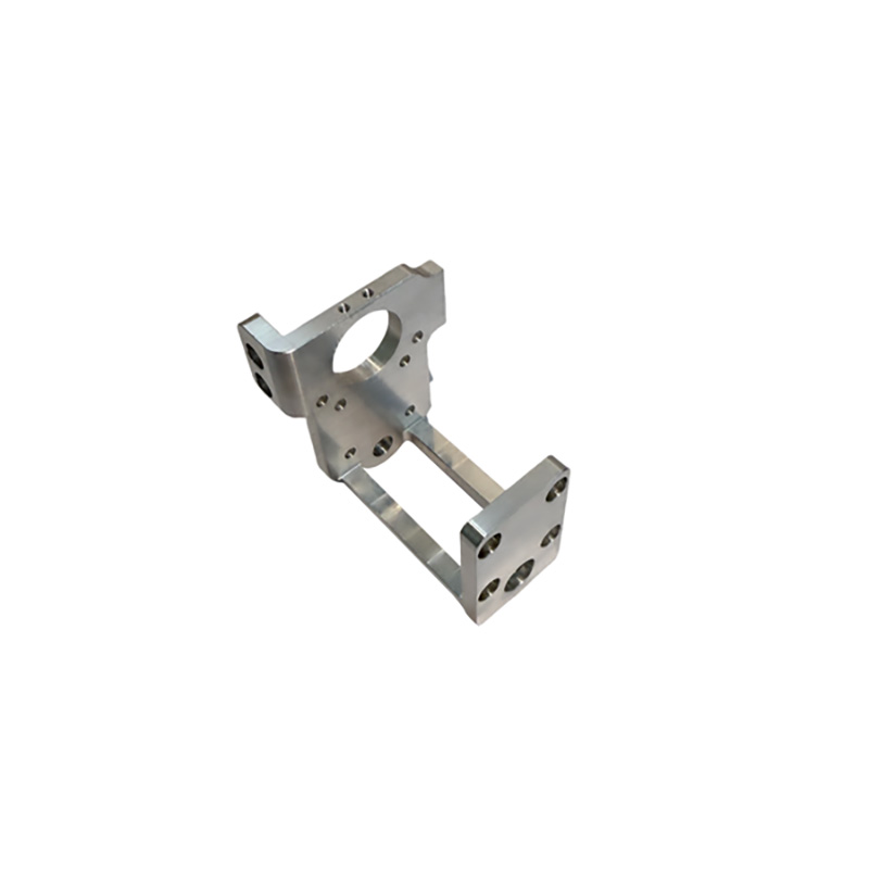
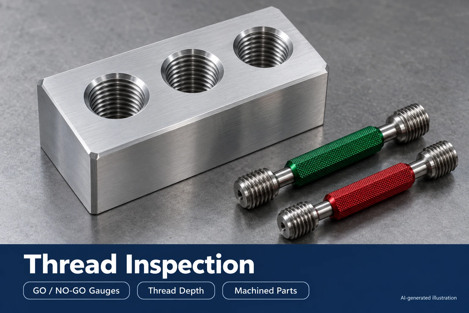
For threads, confirm the final thread class, gauging stage, treatment of internal and external threads, and permitted masking transitions. A successful gauge check does not replace evaluation of coating coverage, edge condition or the rest of the assembly. For a guide-shaft support, also consider whether the slot and clamp load change the bore condition when assembled.
Finished-part acceptance checklist
- Record the alloy and material condition used for the approved finishing route.
- Confirm the coating specification, thickness requirement, sealing and color where relevant.
- Identify dimensions that apply after finishing and define the datum setup.
- Check critical bores, shafts and threads in the delivered surface condition.
- Verify masking boundaries and inspect transitions that can affect seating or movement.
- Compare an identified finished sample with the mating part where functional approval is required.
- Review the allowance again if alloy, pretreatment, finish or a critical process changes.
What should engineering send with the RFQ?
Include the controlled drawing, CAD, mating-component information, required final fit, proposed finish and quantities. Ask the supplier to separate unresolved finishing assumptions from confirmed quotation scope. This is particularly useful for robotic joints, machinery guides and lightweight drone assemblies, where a small interface change may matter more than the appearance of the outer surface.
Review the finished interface before production
Explore our guide-shaft support bracket example, manufacturing solutions and quality and inspection guide. Send the drawing and coating requirements to tonyzhou@lxcet.com. LXCET reviews process feasibility and acceptance scope for the specific part; no single coating allowance applies to every project.